Excell MCDSe series
Rel. 1
alsa apparecchi medicali srl 9
535mA on the load indicated before. Check the right supply of power, by setting also other lower values and,
if necessary, set the R81 pot again.
Set the Auto Pure monopolar function at 200; at the selected monopolar output, connect a 200ohms load;
switch the equipment on, and set the R30 pot in order to obtain an output current of 1.0A. Verify the
correspondence existing between the selection and the R.F. power delivery, even in the Pure Cut mode and
in the bipolar Blend mode.
MATCHING OF THE POWER MOSFETS DRAIN CURRENT
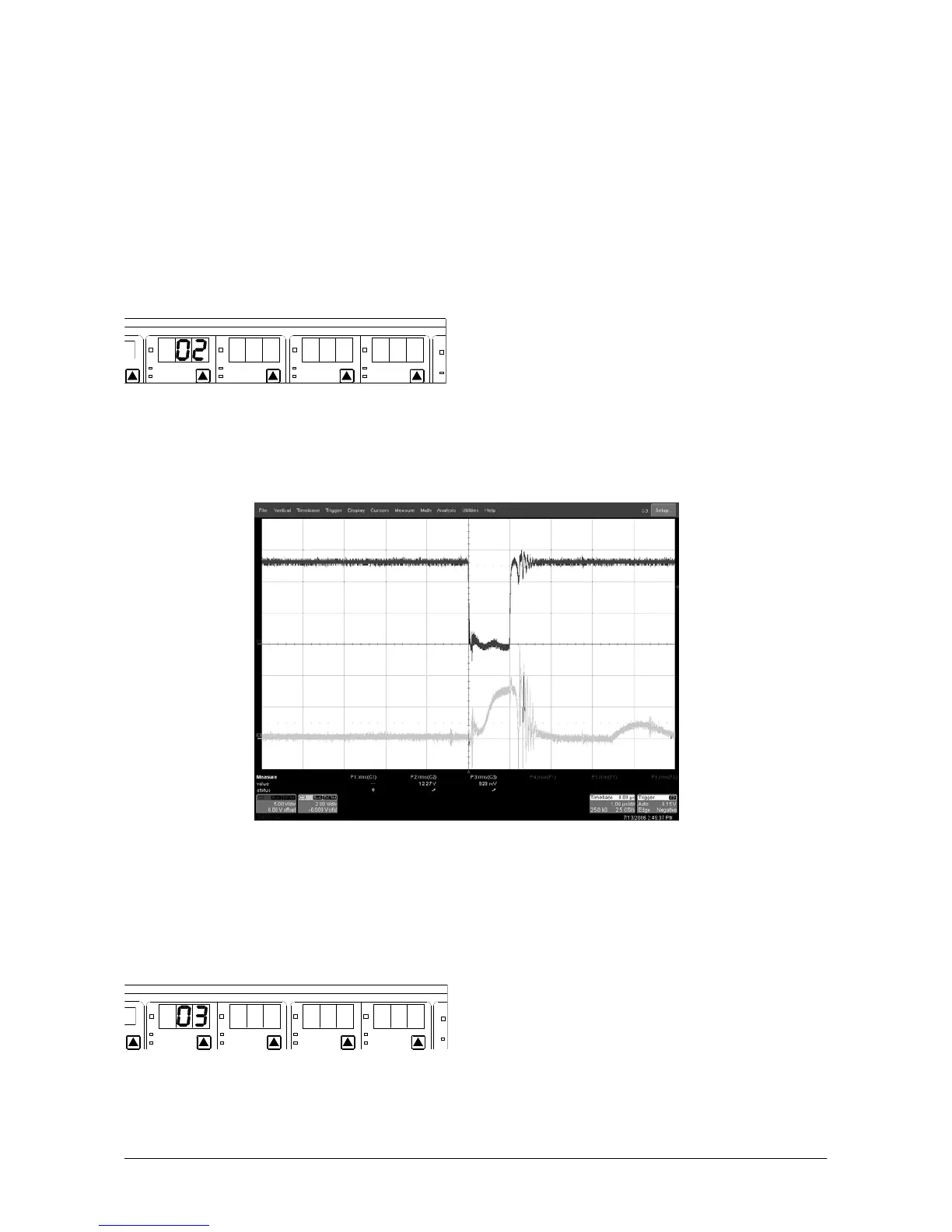
Press the CAL button; when the displays blink, set the monopolar Cut section, as shown into the Figure:
MONOPOLAR BIPOLAR
AM
PURE
BLEND-1
FULG FORCED
PIN POINT CONTACT
PURE
BLEND
MICRO CV
MICRO HC
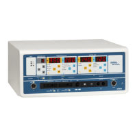
Press the CAL button in order to interrupt the displays blinking, and set 35 in the SPRAY mode. Connect a
200ohms non-inductive load at the output of the equipment. Connect the probes of the oscilloscope to the
signals indicated with DRIVRF and IPKISOG on the R.F. power generator board (Alsa code: 801465), and
check the following waveforms:
Just in case the signals measured by the probes are different, it is necessary to change the position of the
jumpers connections J1 and J4, placed on the R.F. power generator board (from horizontal to vertical
position, and vice versa). At the end, put the R.F. power generator board in its right position.
CALIBRATION OF THE OUTPUT VOLTAGE PEAK FOR EACH MODE
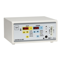
Press the CAL button; when the displays blink, set the monopolar Cut section, as shown into the Figure:
MONOPOLAR BIPOLARRAM
PURE
BLEND-1
FULG FORCED
PIN POINT CONTACT
PURE
BLEND
MICRO CV
MICRO HC
Press the CAL button in order to interrupt the displays blinking.
Connect the high voltage probe to the selected output; in order to perform this calibration, it is necessary to
use standard length cables connected to the output (even better if placed according to the Standard CEI EN