Description and Functionalities
General Description of the Switchgear
P12--0001EN/02
2/6
01--2011
© ALSTOM 2010. All rights reserved. Information contained in this document is indicative only. No representation or warranty is given or should be relied on
that it is complete or correct or will apply to any particular project. This will depend on the technical and commercial circumstances. It is provided without
liability and is subject to change without notice. Reproduction, use or disclosure to third parties, without express written authority, is strictly prohibited.
GRID
Circuit breaker pole
Description
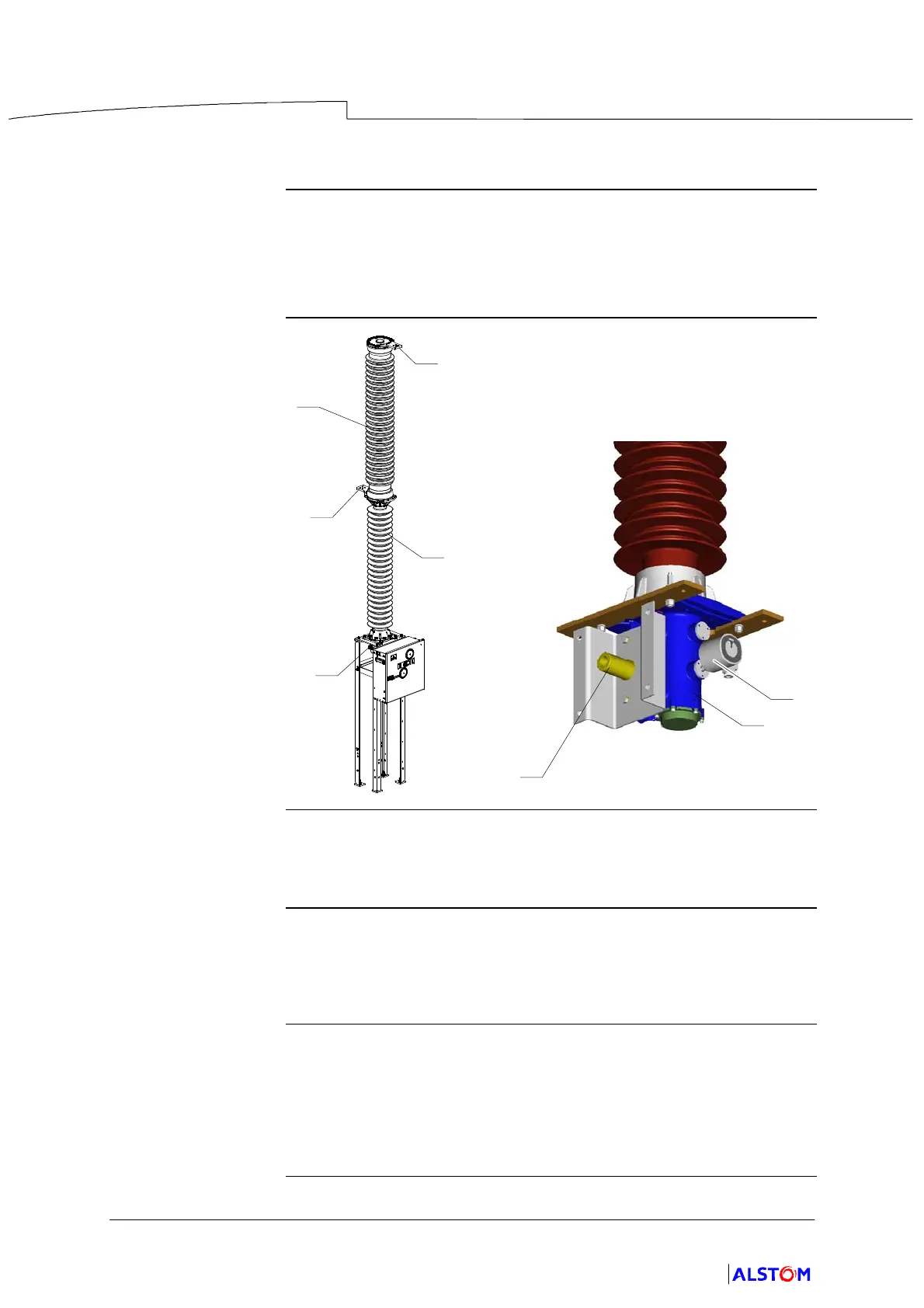
The circuit breaker pole is made up of three main components :
D The breaking chamber (1).
D The support column (2).
D The mechanism casing (3).
Illustration
2
1
5
5
3
7
4
3
Breaking
chamber
The pole comprises a breaking chamber (1), in ceramic casing, placed
vertically, with the upper end of each fitted with a power supply terminal
(5).
Support Column
Comprising one or more ceramic insulators, the support column (2) is
used to provide earthing insulation for the circuit breaker and encloses the
insulating operating rod, attached to the moving parts of the breaking
chamber.
Mechanism casing
A casing (3), located at the base of the column, encloses the operating
rod--crank attached to the moving parts.
The filling and monitoring device for the SF
6
(7) gas is also located in the
casing.
An external sleeve (4) mechanically connects the pole to the operating
mechanism.