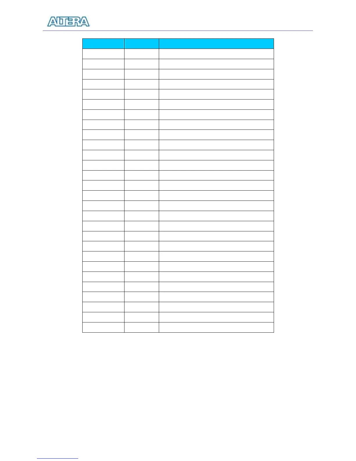
Description
HEX0[0] PIN_J2 Seven Segment Digit 0[0]
HEX0[1] PIN_J1 Seven Segment Digit 0[1]
HEX0[2] PIN_H2 Seven Segment Digit 0[2]
HEX0[3] PIN_H1 Seven Segment Digit 0[3]
HEX0[4] PIN_F2 Seven Segment Digit 0[4]
HEX0[5] PIN_F1 Seven Segment Digit 0[5]
HEX0[6] PIN_E2 Seven Segment Digit 0[6]
HEX1[0] PIN_E1 Seven Segment Digit 1[0]
HEX1[1] PIN_H6 Seven Segment Digit 1[1]
HEX1[2] PIN_H5 Seven Segment Digit 1[2]
HEX1[3] PIN_H4 Seven Segment Digit 1[3]
HEX1[4] PIN_G3 Seven Segment Digit 1[4]
HEX1[5] PIN_D2 Seven Segment Digit 1[5]
HEX1[6] PIN_D1 Seven Segment Digit 1[6]
HEX2[0] PIN_G5 Seven Segment Digit 2[0]
HEX2[1] PIN_G6 Seven Segment Digit 2[1]
HEX2[2] PIN_C2 Seven Segment Digit 2[2]
HEX2[3] PIN_C1 Seven Segment Digit 2[3]
HEX2[4] PIN_E3 Seven Segment Digit 2[4]
HEX2[5] PIN_E4 Seven Segment Digit 2[5]
HEX2[6] PIN_D3 Seven Segment Digit 2[6]
HEX3[0] PIN_F4 Seven Segment Digit 3[0]
HEX3[1] PIN_D5 Seven Segment Digit 3[1]
HEX3[2] PIN_D6 Seven Segment Digit 3[2]
HEX3[3] PIN_J4 Seven Segment Digit 3[3]
HEX3[4] PIN_L8 Seven Segment Digit 3[4]
HEX3[5] PIN_F3 Seven Segment Digit 3[5]
HEX3[6] PIN_D4 Seven Segment Digit 3[6]
Table 4.4. Pin assignments for the 7-segment displays.
4.4 Clock Inputs
The DE1 board includes three oscillators that produce 27 MHz, 24Mhz, and 50 MHz clock signals.
The board also includes an SMA connector which can be used to connect an external clock source
to the board. The schematic of the clock circuitry is shown in Figure 4.8, and the associated pin
assignments appear in Table 4.5.