4
2.1 Layout and Components
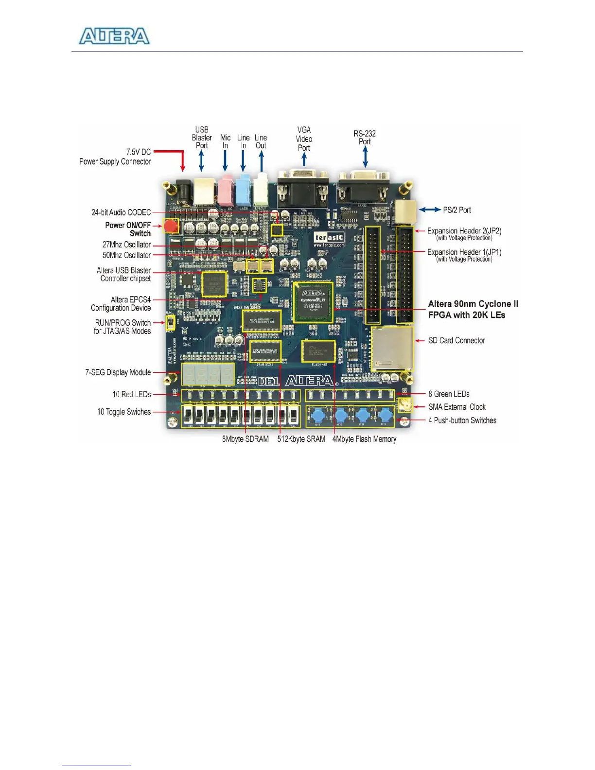
A photograph of the DE1 board is shown in Figure 2.1. It depicts the layout of the board and
indicates the location of the connectors and key components.
Figure 2.1. The DE1 board.
The DE1 board has many features that allow the user to implement a wide range of designed
circuits, from simple circuits to various multimedia projects.
The following hardware is provided on the DE1 board:
• Altera Cyclone
®
II 2C20 FPGA device
• Altera Serial Configuration device – EPCS4
• USB Blaster (on board) for programming and user API control; both JTAG and Active Serial
(AS) programming modes are supported
• 512-Kbyte SRAM
• 8-Mbyte SDRAM