37
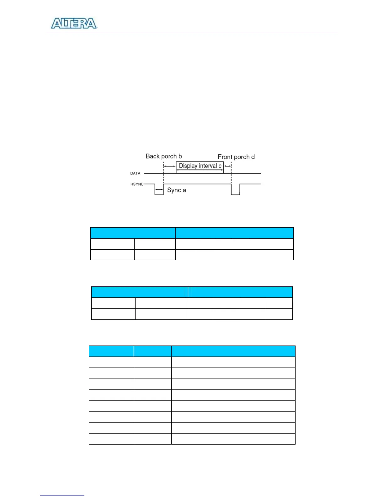
During the data display interval the RGB data drives each pixel in turn across the row being
displayed. Finally, there is a time period called the front porch (d) where the RGB signals must
again be off before the next hsync pulse can occur. The timing of the vertical synchronization (vsync)
is the same as shown in Figure 4.12, except that a vsync pulse signifies the end of one frame and the
start of the next, and the data refers to the set of rows in the frame (horizontal timing). Figures 4.13
and 4.14 show, for different resolutions, the durations of time periods a, b, c, and d for both
horizontal and vertical timing.
The pin assignments between the Cyclone II FPGA and the VGA connector are listed in Table 4.8.
An example of code that drives a VGA display is described in Sections 5.2 and 5.3.
Figure 4.12. VGA horizontal timing specification.
VGA mode Horizontal Timing Spec
Configuration Resolution(HxV)
25 (640/c)
Figure 4.13. VGA horizontal timing specification.
VGA mode Vertical Timing Spec
Configuration Resolution (HxV) a(lines)
Description
VGA_R[0] PIN_D9 VGA Red[0]
VGA_R[1] PIN_C9 VGA Red[1]
VGA_R[2] PIN_A7 VGA Red[2]
VGA_R[3] PIN_B7 VGA Red[3]
VGA_G[0] PIN_B8 VGA Green[0]
VGA_G[1] PIN_C10 VGA Green[1]
VGA_G[2] PIN_B9 VGA Green[2]
VGA_G[3] PIN_A8 VGA Green[3]