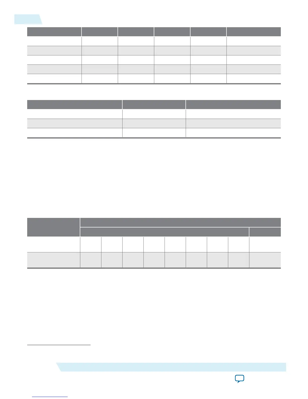
LFR[4] LFR[3] LFR[2] LFR[1] LFR[0] Setting (Decimal)
1 0 1 0 0 20
1 1 0 0 0 24
1 1 0 1 1 27
1 1 1 0 0 28
1 1 1 1 0 30
Table 4-4: Loop Filter High Frequency Capacitor Control
LFC[1] LFC[0] Setting (Decimal)
0 0 0
0 1 1
1 1 3
Related Information
• Programmable Bandwidth on page 2-19
• Programmable Bandwidth with Advanced Parameters on page 4-10
• Programmable Bandwidth Parameter Settings on page 6-2
Bypassing PLL Counter
Bypassing a PLL counter results in a multiplification (M counter) or a division (N, C0 to C4 counters) factor
of one.
Table 4-5: PLL Counter Settings
Description
PLL Scan Chain Bits [0..8] Settings
LSB MSB
PLL counter
bypassed
X X X X X X X X 1
(9)
PLL counter not
bypassed
X X X X X X X X 0
(9)
To bypass any of the PLL counters, set the bypass bit to 1. The values on the other bits are ignored.
(9)
Bypass bit
4-14
Bypassing PLL Counter
UG-M10CLKPLL
2015.06.12
Altera Corporation
MAX 10 Clocking and PLL Implementation Guides
Send Feedback