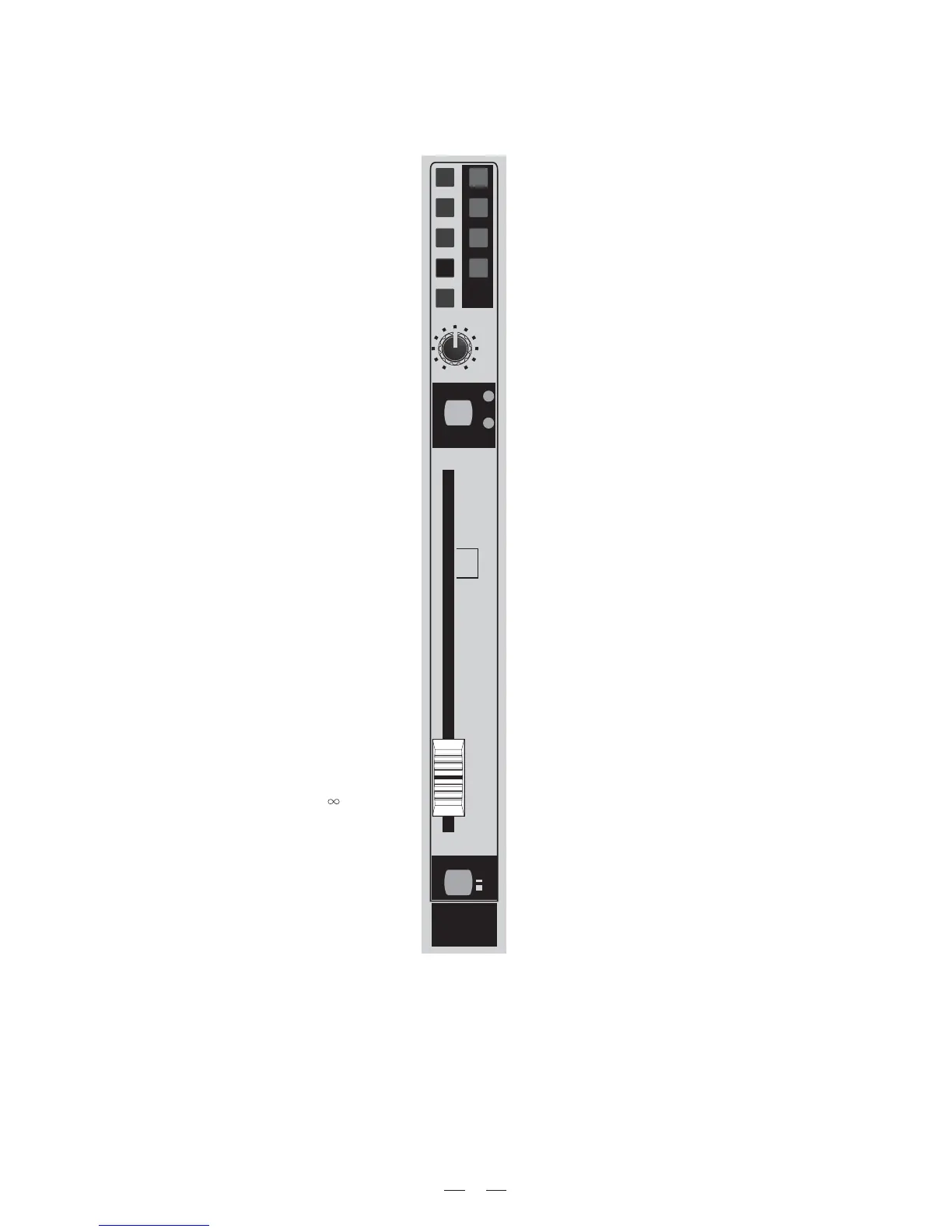
The assign section is useful to manage the output assignment to several outputs, as well as direct out, to listen "in
solo" a channel and to mute or not a channel signal.
OUTPUT Assign 1/2 3/4 5/6 7/8 L/R
These switches allow the sound engineer
to address the signal to selected audio path.
The odd/even numbered switches are used
to send the signal to sub-groups while L/R
switch sends the signal directly to Main Mix
output.
Please check the "technique & trouble-
shooting" section of this owner's manual
for further details about the way to use
those switches.
PAN
This pot allows the sound engineer to place
the channel signal in a stereo front from
hard left to hard right. Of course you can
use it also to "move" the channel signal in
stereo front to create spatial effects.
MUTE
You can use the MUTE switch to mute the
channel signal when you don't need its
sound. When this large switch is engaged,
it's lit. The signal is still sent only to insert
point, while the direct out is muted too.
Fader
This long coarse fader will give to the sound
engineer the ability to accurately manage
the channel output level from - up to
+10dB.
M1, M2, M3 & M4
These switches are very useful to manage the
sound in a fast and reliable way. You can use M1,
M2, M3 and M4 to program four MUTE memories.
This feature is important to give an immediate
control over some channels that are not used all
show long (e.g. some instruments played just in
some songs, the voice of the presenter, etc.) and
to immediately recall al the mixers status.
See section 7 of this owner's manual for the pro-
cedure to store and recall the four Mute Groups
memories.
-20 & CLIP LEDs
These LEDs are very useful to control the be-
haviour of the channel signal path after the insert
point, the EQ section and the fader. So you could
notice the fader CLIP LED turned on while the pre-
amp CLIP is not lit, or vice-versa. In both cases
the presence of two CLIP LEDs will help the sound
engineer to immediately detect where is the pro-
blem.
PFL/Solo switch
This switch allows the sound engineer to control
the channel signal. The PFL (pre-fade listen) sig-
nal is pre-fader and mono while Solo stands for
SIP (Solo In Place), the signal is post-fader, pla-
ced in stereo front and it "opens" all the circuits
of related effect. When this large switch is engaged,
it's illuminated to give you an immediate visual
control of which, and how many channels are in
solo.
When the MASTER SOLO switch is engaged this
switch acts in SOLO mode and mutes all other
channels
14
[ Typhoon Mono Input Channels ]
MUTE
PFL/SOLO
ON
OFF
GR1-GR2
M1
GR3-GR4
M2
GR5-GR6
M3
GR7-GR8
M4
MUTE
L/R
CLIP
-20
CH 1CH 1
10
5
5
10
20
30
40
50
60
-
0
8
PAN
centre
Right
Left