Improper operation can be hazardous. Ensure that you are familiar with the operation of the
Compressor and the Roller Striker before use.
CAUTION
Start and Stop procedure - Hydraulic Models
1. Refer to the manufacturers Operating Instructions Manual for the start up procedure for Hydraulic
Power Packs.
2. Ensure that before starting the Power pack that all connections are tight and that the control valve
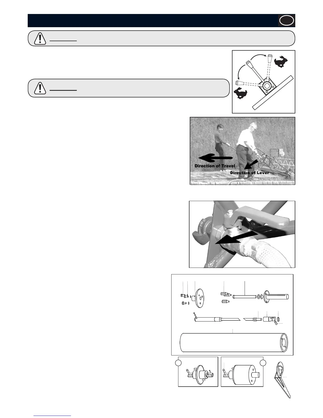
on the striker is in the NEUTRAL position (See Fig. 1)
N
Fig.1
Always ensure the operators are in control of the Roller Striker before
moving the lever on the Power Pack from Bypass to Flow to prevent
the striker operating unexpectedly.
CAUTION
3. Ensure that you move the control lever to the correct position for the direction of
travel (See Fig. 2)
4. This will ensure that the striker is rotating in the opposite direction to that in
which it is being pulled.
5. To start the roller striker, move the Control Lever slowly to the DRIVE
position as indicated below (See Fig. 2)
6. To stop the roller striker, move the Control Lever to the NEUTRAL position
(See Fig. 1)
Start and Stop procedure - Pneumatic Models
1. Refer to the manufacturers Operating Instructions Manual for the start up
procedure for Compressors.
2. Ensure that before starting the Compressor that all connections are tight and
that the control valve on the striker is in the CLOSED position.
3. To start the roller striker, move the Control Lever to the OPEN position.
4. To stop the roller striker, move the Control Lever to the CLOSED position.
Fig.2 shows the Pneumatic Contol Lever in the OPEN position, with arrow indicating direction for CLOSED position.
Assembly of Sectional Tube.
Using the 3 tubes as individuals with the short drive end or combining 2 lengths
with the adaptor plate it is possible to make tubes of the following lengths : 2.2,
3.2, 4.2, 5.2, 6.2 and 7.2 metres.
Tools required:
- 24mm Socket (19.1.270) - 17mm Socket (19.1.404)
- Torque Wrench (19.1.827) - Special Tool (150040)
Assembly Instructions
1. Remove setscrews (A), washers (B) and drive plate (C).
2. Fit special tool (D) around hexagon spacers (E).
3. Slacken off the tension screw (F) until the connector (G) is fully
exposed.
4. Check the tension of threaded dowel (H) & (I).
5. Screw the link rod (G) up to the nut (J) and then unscrew 1/2 a
turn. This will allow you to connect the two ends tightly together.
6. Connect the adaptor plate (K) or short drive end (L) to the
connector (G) and slide the securing ring (M) into the centre
groove.
7. Push the adaptor plate (K) into the tube (N).
8. With the special tool (D) still in position, tighten the tension screw
(F) to 100Nm.
9. Replace the end plate (C), washers (B) and setscrews (A).
10. Repeat the procedure to connect the second length of tube if
required.
11. For disassembly, reverse the procedure.
Fig.3