CONTROL UNITS UTR230868 / UTR400868 2525
SETTINGS
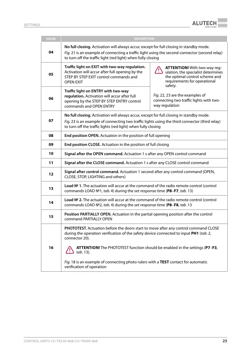
VALUE DESCRIPTION
04
No full closing. Activation will always accur, except for full closing in standby mode.
Fig.21 is an example of connecting a trac light using the second connector (second relay)
to turn o the trac light (red light) when fully closing
05
Trac light on EXIT with two-way regulation.
Activation will accur after full opening by the
STEP BY STEP EXIT control commands and
OPEN EXIT
Y
ATTENTION! With two-way reg-
ulation, the specialist determines
the optimal control scheme and
requirements for operational
safety.
Fig.22, 23 are the examples of
connecting two trac lights with two-
way regulation
06
Trac light on ENTRY with two-way
regulation. Activation will accur after full
opening by the STEP BY STEP ENTRY control
commands and OPEN ENTRY
07
No full closing. Activation will always accur, except for full closing in standby mode.
Fig.23 is an example of connecting two trac lights using the third connector (third relay)
to turn o the trac lights (red light) when fully closing
08
End position OPEN. Actuation in the position of full opening
09
End position CLOSE. Actuation in the position of full closing
10
Signal after the OPEN command. Actuation 1 s after any OPEN control command
11
Signal after the CLOSE command. Actuation 1 s after any CLOSE control command
12
Signal after control command. Actuation 1 second after any control command (OPEN,
CLOSE, STOP, LIGHTING and others)
13
Load 1. The actuation will accur at the command of the radio remote control (control
commands LOAD 1, tab.4) during the set response time (P8–F7, tab.13)
14
Load 2. The actuation will accur at the command of the radio remote control (control
commands LOAD 2, tab.4) during the set response time (P8–F8, tab.13
15
Position PARTIALLY OPEN. Actuation in the partial opening position after the control
command PARTIALLY OPEN
16
PHOTOTEST. Actuation before the doors start to move after any control command CLOSE
during the operation verication of the safety device connected to input PH1 (tab.2,
connector 20).
Y
ATTENTION! The PHOTOTEST function should be enabled in the settings (P7–F3,
tab.13).
Fig.18 is an example of connecting photo rulers with a TEST contact for automatic
verication of operation