CONTROL UNITS UTR230868 / UTR400868 55
PREPARATION FOR INSTALLATION
2.2 SPECIFICATIONS
Table1
FEATURE CUTR230868 CUTR400868
Supply voltage 230V ± 10% ~ 400V ± 10% 3N~
Network frequency, Hz 50
Maximum drive power, kW 1 1.5
Maximum power consumption in standby mode
(without additional devices), W
3 4
Power supply for additional devices
12V DC / max.150 mA
24 V DC / max.250 mA
Cross section of wires connected to connectors max.2.5 mm
Radio control
868.35MHz ± 0.15MHz / dynamic code /
maximum of 32 remotes
Protection degree IP65 (professional installation)
Operating temperature range,° C −30 … +65
Gross weight, kg 2.7 2.9
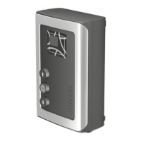
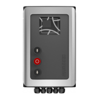
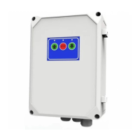
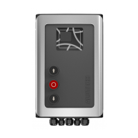
Overall and mounting dimensions of the control unit are in g.2, 3. Fig.3 shows the dimensions if
installation is on the unit body of external xings.
Service life is 8 years, but not more than 100,000 full cycles when performing maintenance, in-
stallation and operation rules.
3. PREPARATION FOR INSTALLATION
1. Read section ‘1. Safety rules and warnings’. Make sure that all rules and requirements are
followed and fulfilled.
2. Determine the location, where each drive system device will be installed. An example of
a typical scheme of automation of sectional balanced industrial doors with a wicket is in
fig.4. Determine the installation locations of the control devices together with the user
(owner).
3. Determine which devices (for safety, control, signaling, etc.) and accessories (electrical
cables, cablechannels, connectors, junction boxes, fasteners, etc.) that are not included in
the complete kit must be purchased separately. Identify the electrical circuit, according to
which all drive devices will be connected.
Y
ATTENTION! Depending on the conditions and doors operational mode, identify corresponding
safety devices, which are dened by safety regulations of your country or EN12453 standard in
accordance with safety type (minimal safety level). When delivered, the product is designed for
use in manual mode (tab.13, setting P3-F1).
4. Lay electrical cables in accordance with current regulations to the locations where the
drive system devices are to be installed.
5. Install the required number of cableentries at the bottom of the control unit body
(PG13.5 and PG9 entries are included in the complete kit). Previously drill apertures in the
indicated places of the unit body (when the cover is closed) according to dimensions of
the cableentry or cut them out (for example, with a sharp screwdriver in several places
ofone aperture). Do it carefully.