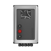
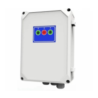
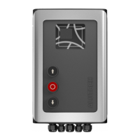
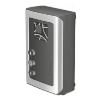
CONTROL UNITS UTR230 / UTR4009090
PREPARATION FOR INSTALLATION
Overall and mounting dimensions of the control unit are in Figure 2, Figure 3. Figure 3 shows the
dimensions if installation is on the unit body of external xings.
Service life is 8 years, but not more than 100,000 full cycles when performing maintenance, in-
stallation and operation rules.
3. PREPARATION FOR INSTALLATION
1. Read section ‘1. Safety rules and warnings’. Make sure that all rules and requirements are
followed and fulfilled.
2. Determine the location, where each drive system device will be installed. An example of
atypical scheme of automation of sectional balanced industrial doors with a wicket is in
Figure4. Determine the installation locations of the control devices together with the user
(owner).
3. Determine which devices (for safety, control, signaling, etc.) and accessories (electrical
cables, cable channels, connectors, junction boxes, fasteners, etc.) that are not included in
the complete kit must be purchased separately. Identify the electrical circuit according to
which all drive devices will be connected.
Y
ATTENTION!Depending on the conditions and doors operational mode, identify
corresponding safety devices, which are dened by safety regulations of your
country or EN 12453 standard in accordance with safety type (minimal safety
level). When delivered, the product is designed for use in manual mode (Table 13,
setting P3–F1).
4. Lay electrical cables in accordance with current regulations to the locations where the
drive system devices are to be installed.
5. Install the required number of cable entries at the bottom of the control unit body
(PG13.5 and PG9 entries are included in the complete kit). Previously drill apertures in the
indicated places of the unit body (when the cover is closed) according to dimensions of
the cable entry or cut them out (for example, with a sharp screwdriver in several places
ofone aperture). Do it carefully.
4. INSTALLATION
Install the control unit on a vertical surface within the visibility of doors (next to doors) at aheight
of at least 1.5 m (Figure 4) at a safe distance from the moving elements of doors. It is recommend-
ed to install the control unit relative to doors on the installation side of drive. The cable entries
of the control unit must face down. The installation location of the control unit must ensure the
opening (turn to the left) of the cover of the unit body.
Y
Type of fasteners (dowels, self-tapping screws, etc.), install depending on the material and thickness
of the surface (wall) on which the control unit is installed. For xing the unit, there are four dowels
with screw 5 in the kit (Figure 1). If they do not t, then purchase the required fasteners yourself.
There are two ways to install the control unit:
OPTION 1. Installation with four hidden mounting apertures of the unit (Figure 2). To access the
apertures, it is necessary to open the cover of the unit body by unscrewing four screws (Figure
5), previously carefully removing the cover frame. To mark apertures on the surface, use tem-
plate 7 (Figure 1) from the unit kit.