CONTROL UNITS UTR230 / UTR400 113113
INSCRIPTION
7. INSCRIPTION
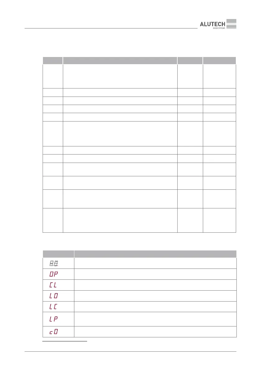
Table 17 — LEDs 19 (Figure 8, Figure 9)
LED INSCRIPTION PURPOSE LIGHT ON LIGHT OFF
LR
Radio control command (the LED lights up in red if the
remote control is not recorded or the control command is
not assigned to the control button / lights up in green if
the control command is assigned to the control button)
Is supplied Is not supplied
LOP Command to open (input OP, connector 20) Is supplied Is not supplied
LCL Command to close (input CL, connector 20) Is supplied Is not supplied
LSBS Command to open, stop, close (input SBS, connector 20) Is supplied Is not supplied
LP Command to partially open (input P, connector 20) Is supplied Is not supplied
LS
Safety device in the STOP circuit:
• input S, connector 20
• connector 18 or contacts IN_S and O_S of connector 11
(section ‘5.2. Connection of switches/ drive encoder’)
Is activated Is not activated
LA Input command A (connector 20) Is supplied Is not supplied
LPH1 Photocell safety device (input PH1, connector 20) Is activated Is not activated
LCL.L
End position CLOSED
(for drive with switches input CL.L, connector 16)
Closed Not closed
LOP.L
End position OPEN
(for drive with switches input OP.L, connector 16)
Open Not open
LP.L*
Disabling the built-in obstacle detection system P5–F1
(Table 13). For drive with switches, the releasing of input
P. L , connector 16)
Is turned o Is not turned o
L5.L
Disabling the safety edge P5–F7 (Table 13) and / or the slow
speed starting P5–P9.
For drive with switches, the releasing of input P.L,
connector 16)
Is turned o Is not turned o
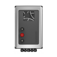
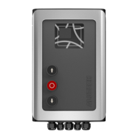
Table 18 — Control panel inscription 14 (Figure 8, Figure 9)
INSCRIPTION DESCRIPTION
Standby mode (display shows one dot)
Opening
Closing
The end position OPEN (for drive with switches, input OP.L is activated connector 20)
The end position CLOSED (for drive with switches, input CL.L is activated connector 20)
Partially open position (by the input command P of the connector 20 or by the
command PARTIALLY OPEN of the radio remote control)
Opening command is activated
* Only for control unit CU-TR230.