CONTROL UNITS UTR230 / UTR400 9191
ELECTRICAL CONNECTIONS
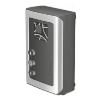
OPTION 2. Installation with four external fasteners (Figure 3). On the base of the control unit
body, use screws 4 (Figure 1) to install at the required mounting angle 3 (Figure 1). Then mark
the xing points on the mounting surface and x the unit.
5. ELECTRICAL CONNECTIONS
Y
ATTENTION! For electrical connections make sure that the mains power is disconnected (cir-
cuit breaker of the mains power is o)!
Follow electrical safety regulations!
Y
Use a puller to remove the connectors. Gently pull with the puller by the connector (Figure 6),
ifnecessary, in several locations along the length of the connector.
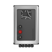
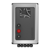
The door control buttons and the display window are located on the unit body cover (Figure 7).
The buttons are connected to the electronic module of the unit by the manufacturer.
5.1 NETWORK AND ELECTRIC DRIVE CONNECTIONS
The network connection is performed to connector 1 of the unit (CU-TR230 — Figure 8,
CU-TR400 — Figure 9). L is phase (phases), N is neutral. Protective earth is connected to connector 2.
Y
When connecting to the network, there should be provided a device disconnecting all poles
from the network (for instance, automatic circuit breaker), which ensures full disconnection
under conditions of over-voltage category III. The device should be installed in accordance
with Electrical Installations Code and located at easily accessible place, at convenient and safe
height (1.5–1.9 m).
The electric drive is connected to connector 10.
The connection of connectors 4 and 12 is performed by the manufacturer
• Network and electric drive TP series (230V ~) connection to the CU-TR230 control unit is
presented in Figure 10.
• Network and electric drive TP series (400V 3~) connection to the CU-TR400 control unit is
presented in Figure 11.
Y
When connecting the electric drive to the control unit, rst read the section on electrical con-
nections of the drive manual. Identify the required cable and the wire marking of cable sup-
plied with the drive.
5.2 CONNECTION OF SWITCHES / DRIVE ENCODER
• Connection a driver TR series with mechanical switches is shown in Figure 12.
Limitswitches(B) of drive are connected to OP.L and CL.L contacts. Function switches (A)
ofdrive are connected to 5.L and P.L contacts, which must be used when switching on in
the unit menu the settings P5–F7 and P5–F1 (Table 13), respectively. ontact P.L is not used
in the CU-TR400 control unit!
Y
Make sure that connector 18 is installed with a crossbar (is included in complete kit).
Ifthere is no connector with a crossbar, connect a crossbar between the IN_S and O_S
contacts of connector 16. When connecting the electric drive to the control unit, rst
read the section on electrical connections of the drive manual. Identify the required
cable and the wire marking of cable supplied with the drive