CONTROL UNITS UTR230 / UTR400 9393
ELECTRICAL CONNECTIONS
CONNECTOR CONTACT DESCRIPTION
20
SE
Security resistive edge connection input 8.2kOhm (Figure 14, 8K2) or optical
safety edge connection (Figure 15, OSE). In the settings (Table 13, P7–F4), the
type of edge (sensor) is set. Contact of the door leaf with an obstacle when
closing (actuation of the installed sensor) will stop the door movement and
then open it (Table 13, P5–F5)
PH1
Security device input (photocells, Figure 16) with normally closed contact
(NC). Actuation when closing will stop the door movement and then open it
(Table13, P5–F5), or block the start of closing
PHT
An output for automatic verication the operation of photocells (PHOTOTEST)
connected to the input PH1. In the settings (Table 13, P7–F3), the PHOTOTEST
is enabled. Before starting the movement, briey turning o, then turning on
the power of photocells, an automatic verication of the photocell operation is
performed.
An example of a scheme for connecting photocells with a power o of the
photocell transmitter is shown in Figure 16. An example of a scheme for
connecting photocells with a transmitter powered by batteries is shown in
Figure 17
7–9
J1.1– J1.3
Normally open (NO) relay
contact
Potential-free relay outputs (dry contact).
Maximum load: no more than 3A.
The relay operating mode is set in the settings
(Table 13, P3–F4…F6). The relay operating
modes are described in Table 14
J2.1– J2.3 General relay contact
J3.1– J3.3
Normally closed (NC) relay
contact
11
L (L1)
Outputs 230V / 50Hz for powering additional devices. Maximum load no more
than 3A
N
15
GND Input connection of shielding antenna conductor
ANT
GND
15
RG58
ANT Input connection of signal antenna conductor
17
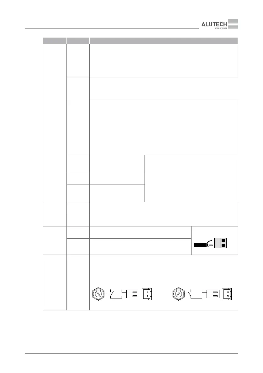
LOCK
Switch connector with key (option). The switch is installed on the unit body.
Using the key, the switch is transferred to the (NC) position, which blocks the
commands of the control devices (unit buttons, control switches, radio remote
controls, etc.), or to the (NO) position, in which control is enabled.
LOCK
17
NC
Control is blocked
17
NO
Control is enabled