Pega 367 with Fanuc 04PC User Pre-installation Guide ©Amada America, Inc.
Print Date 03/07/2001 Revision 4.0 This document available on the World Wide Web at http://www.amada.com Page 16 of 35
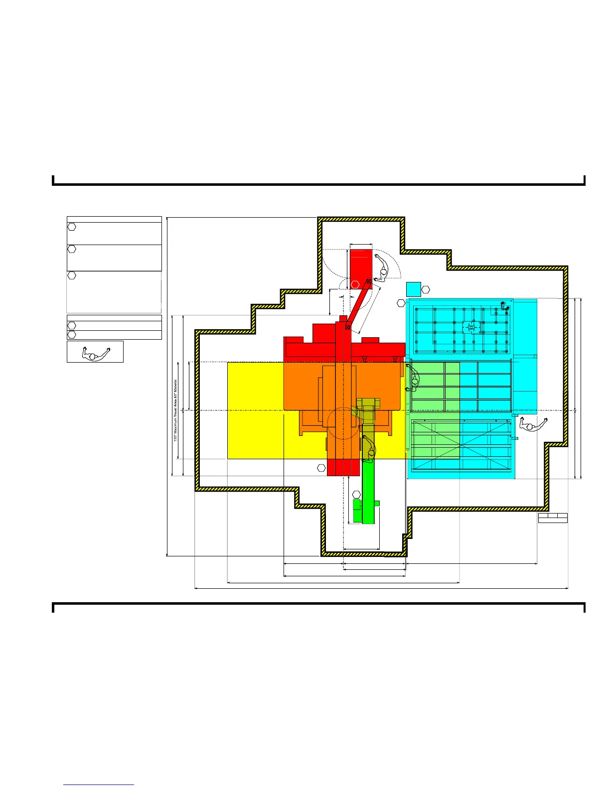
Plan View - Pega 367
with V367hs conveyor and MP1530 loader
463.14" Recommended Safety / Maintenance Area 40" from all components
e
Optional Material Support
Tables Required
Optional Material Support
Tables Required
120" Maximum Travel Area 60" Material
288.00" Maximum Material Travel Area 144" Material
MP1530
Xformer
Forklift access required this area
MP1530
1
Electrical Requirements
Pega 367
230 / 460 / 3 / 60 ±10% 18 kVA
46 amps @ 230 / 3 / 60 VAC
23 amps @ 460 / 3 / 60 VAC
Pega 367
Compressed Air Requirements
80 psi @ 8.8 ft/³min.
P367hs Conveyor
208 - 230 / 460 / 3 / 60 ±10% .8 kVA
2.1 amps @ 208 / 3/ 60 VAC
2.0 amps @ 230 / 3 / 60 VAC
1.0 amps @ 460 / 3 / 60 VAC
MP1530 Loader
29 amps @ 200 / 3 / 60 VAC
200 / 3 / 60 ±10%, 10 Kva
To operate at 230 / 460 VAC a step up
transformer with the following service is
required
26 amps @ 230 / 3 / 60 VAC
13 amps @ 460 / 3 / 60 VAC
MP1530 Loader 75 psi @ 31.8 ft³/min.
Operator Control Station
12" 12" 12"
Scale
E3
E2
E1
A1
A2
E1
A1
A2


 To Next Page