Component Testing Procedures
!
WARNING
To avoid risk of electrical shock, personal injury or death; disconnect power to oven and discharge capacitor
before servicing, unless testing requires power.
RS5320016 Rev. 0 10
Illustration Component Test Results
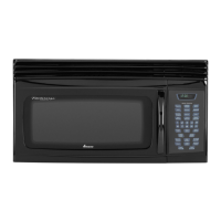
4
COM
230
220
5
6
Transformer
Discharge Capacitor
Remove all wires from terminals.
Measure resistance from:
230 to COM ................................................
220 to COM ................................................
230 to Ground.............................................
220 to Ground.............................................
Terminal 5 to 6............................................
Terminal 4 to Ground..................................
< 1.5 Ω
< 1.5 Ω
Infinite
Infinite
< 1 Ω
Approximately 70 Ω
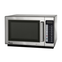
7
8
2
4
3
5
Interlock switch
Door Closed
2
4
7
3
5
8
Primary
Secondary
Monitor
Disconnect wires to switch.
With door open measure resistance from:
Terminal 2 to 3...........................................
Terminal 4 to 5...........................................
Terminal 7 to 8...........................................
With door closed measure resistance from:
Terminal 2 to 3...........................................
Terminal 4 to 5...........................................
Terminal 7 to 8...........................................
Infinite
Infinite
Indicates continuity
Indicates continuity
Indicates continuity
Infinite
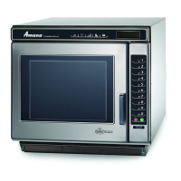
A
Convection blower
motor
Remove wires from motor.
Measure resistance across
terminals A and B .......................................
Approximately 20 Ω
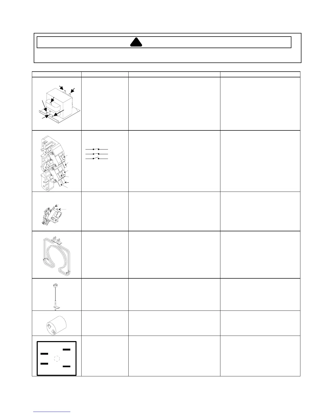
Heating element
assembly
Disconnect wires from terminals.
Measure resistance across heating
element.
Front element 1200 W ......................
Rear element 1500 W ......................
Front element 1100 W ......................
Rear element 1100 W ......................
Indicates continuity
44 Ω
35 Ω
48 Ω
48 Ω
Resistance thermal
device (RTD)
Temperature
0°C (32°F)...................................................
177°C (350°F).............................................
Resistance
1000 Ω
1654 Ω
Lamp receptacle Test continuity of receptacle terminals. Indicates continuity with bulb
screwed in.
IN OUT
Blue
Brown
Brown
Blue
Line filter
Disconnect wire from terminals.
Measure resistance of the following
terminals:
Blue to Blue............................................
Brown to Brown......................................
< 1 Ω
< 1 Ω
 Loading...