Component Testing Procedures
!
WARNING
To avoid risk of electrical shock, personal injury or death; disconnect power to oven and discharge capacitor
before servicing, unless testing requires power.
RS5320016 Rev. 0 11
Illustration Component Test Results
Side touch panel
Continuity is indicated as 100 Ω and
below.
1
Pad
1
2
3
4
5
6
7
8
9
0
Start
Stop/Reset
Trace
3 & 5
3 & 6
3 & 7
3 & 8
3 & 9
4 & 5
4 & 6
4 & 7
4 & 8
4 & 9
5 & 6
6 & 9
Measurement
Continuity
Continuity
Continuity
Continuity
Continuity
Continuity
Continuity
Continuity
Continuity
Continuity
Continuity
Continuity
Top touch panel
Continuity is indicated as 100 Ω and
below.
1
Pad
Preheat
Time Entry
Temp Entry
Power Level
Stage
Program Save
Hidden Pad
Trace
3 & 4
5 & 7
7 & 8
5 & 8
5 & 9
6 & 7
8 & 9
Measurement
Continuity
Continuity
Continuity
Continuity
Continuity
Continuity
Continuity
Wire harness High voltage board
to display module
harness
Test continuity of wires. Indicates continuity
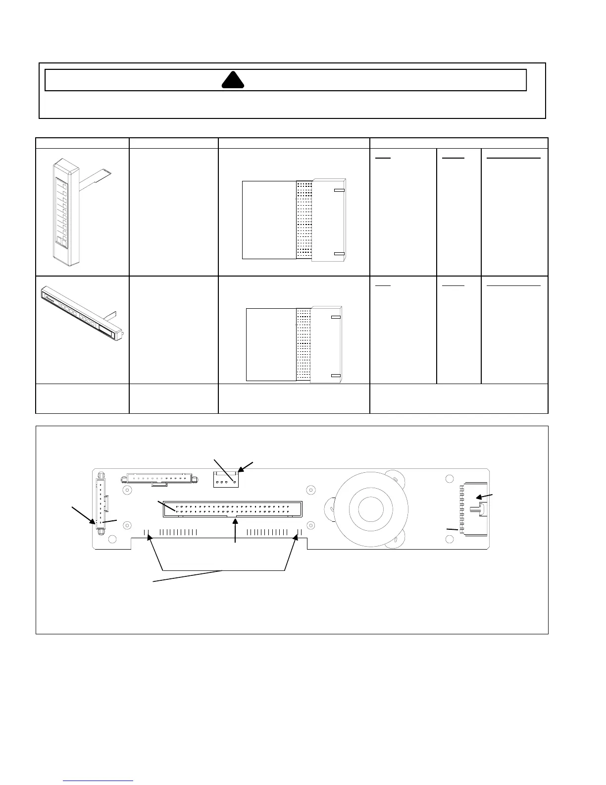
Display board
J1
J5
J6
J4
Pin 1
Pin 1
Pin 1
Pin 1
Side
Touch
Panel
Connector
H.V. board
Connector
Interlock
Connector
Top
Touch
Panel
Connector
3.5 VAC should be indicated whenever the oven is plugged into a power supply.
If voltage is present and no display is indicated, replace display board.
If no voltage is present, check wire harness connections and H.V. board.
 Loading...