SYSTEM OPERATION
16
*MES9* / *CES9 Direct Vent (2-Pipe) & Non-Direct Vent (1-Pipe)
(6
Maximum Allowable Length of Vent/Flue Pipe
2^
108 105 101 97 93 90 86 82
3 126 120 115 110 105 99 94 89
2 55 50 45 40 35 30 25 20
3
127 120 113 106 99 92 85 78
2 30 25 20 15 10 5 N/A N/A
3 72 65 58 51 44 37 30 23
2 30 25 20 15 10 5 N/A N/A
3 72 65 58 51 44 37 30 23
3 72 65 58 51 44 37 30 23
2 60 55 50 45 40 35 30 25
3 168 161 154 147 140 133 126 119
2 30 25 20 15 10 5 N/A N/A
3
113 106 99 92 85 78 71 64
2 N/A N/A N/A N/A N/A N/A N/A N/A
3 65 58 51 44 37 30 23 16
2^ 75 71 67 63 60 56 52 48
3
126 120 115 110 105 99 94 89
3
168 161 154 147 140 133 126 119
2 35 30 25 20 15 10 5 N/A
3 168 161 154 147 140 133 126 119
2 60 55 50 45 40 35 30 25
3 113 106 99 92 85 78 71 64
2 45 40 35 30 25 20 15 10
3 120 113 106 99 92 85 78 71
3 151 144 137 130 123 116 109 102
2
N/A N/A N/A N/A N/A N/A N/A N/A
3 158 151 144 137 130 123 116 109
2 100 95 90 85 80 75 70 65
3 137 130 123 116 109 102 95 88
2 45 40 35 30 25 20 15 10
3 168 161 154 147 140 133 126 119
3 120 113 106 99 92 85 78 71
2 N/A N/A N/A N/A N/A N/A N/A N/A
3 113 106 99 92 85 78 71 64
2 N/A N/A N/A N/A N/A N/A N/A N/A
3 110 103 96 89 82 75 68 61
1) Maximum allowable limits listed on individual lengths for inlet and ue and NOT
a combination.
2) Minimum requirement for each vent pipe is ve (5) feet in length and one elbow/
tee.
3) Tee used in the vent/ue termination must be included when determining the
number of elbows in the piping system.
4) 2 1/2” or 3” diameter pipe can be used in place of 2” diameter pipe.
5) Increased Clearance Congurations using (2) 45 deg. Long Sweep elbows should
be considered equivalent to one 90 deg. elbow.
6) One 90° elbow should be secured to the combustion air intake connection.
Vent/Flue and Combustion Air Pipe Lengths and
Diameters
Refer to the preceding table for applicable length, elbows,
and pipe diameter for construction of the vent/flue and
combustion air intake pipe systems of a non-direct vent
(single pipe) installation. The number of elbows tabulated
represents the number of elbows and/or tees in each (Vent/
Flue & Combustion Air Intake) pipe. Elbows and/or tees used
in the terminations must be included when determining the
number of elbows in the piping systems.
If the combustion air intake pipe is to be installed above a
nished ceiling or other area where dripping of condensate
will be objectionable, insulation of the combustion air pipe
may be required. Use 1/2” thick closed cell foam insulation
such as Armaex or Insultube where required.
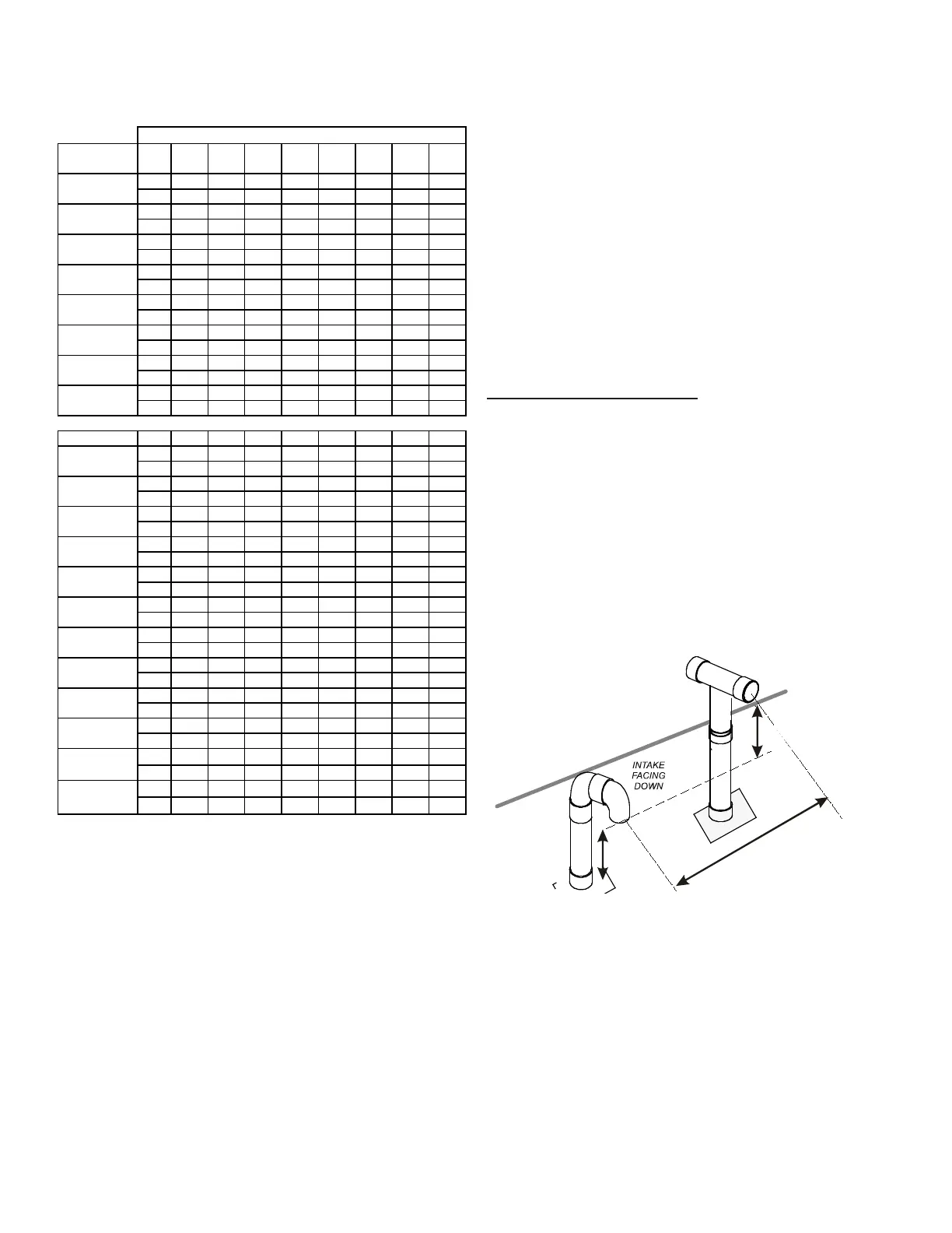
The vent/ue pipe may terminate vertically, as through a roof,
or horizontally, as through an outside wall.
Vertical vent/ue pipe termination should be as shown in the
following gures. Refer to Vent/Flue Pipe and Combustion
Air Pipe - Termination Locations section in this manual or
the installation instructions for details concerning location
restrictions. The penetration of the vent through the roof must
be sealed tight with proper ashing such as is used with a
plastic plumbing vent.
R
L
I
N
E
9
M
AX
-
3
M
I
N
12” MIN
HEIGHT DIFFERENCE
BETWEEN
INTAKE AND VENT
12” MIN TO ROOF OR HIGHEST
ANTICIPATED SNOW LEVEL
 Loading...