SERVICING
39
To aid in identifying these controls, refer to the Primary Limit
Charts in furnace Technical Manual for part number,
temperature setting and color(s) code.
The upow furnaces use two auxiliary limit
switch for control of high temperatures within the furnace or
duct work. This control is preset, nonadjustable and auto
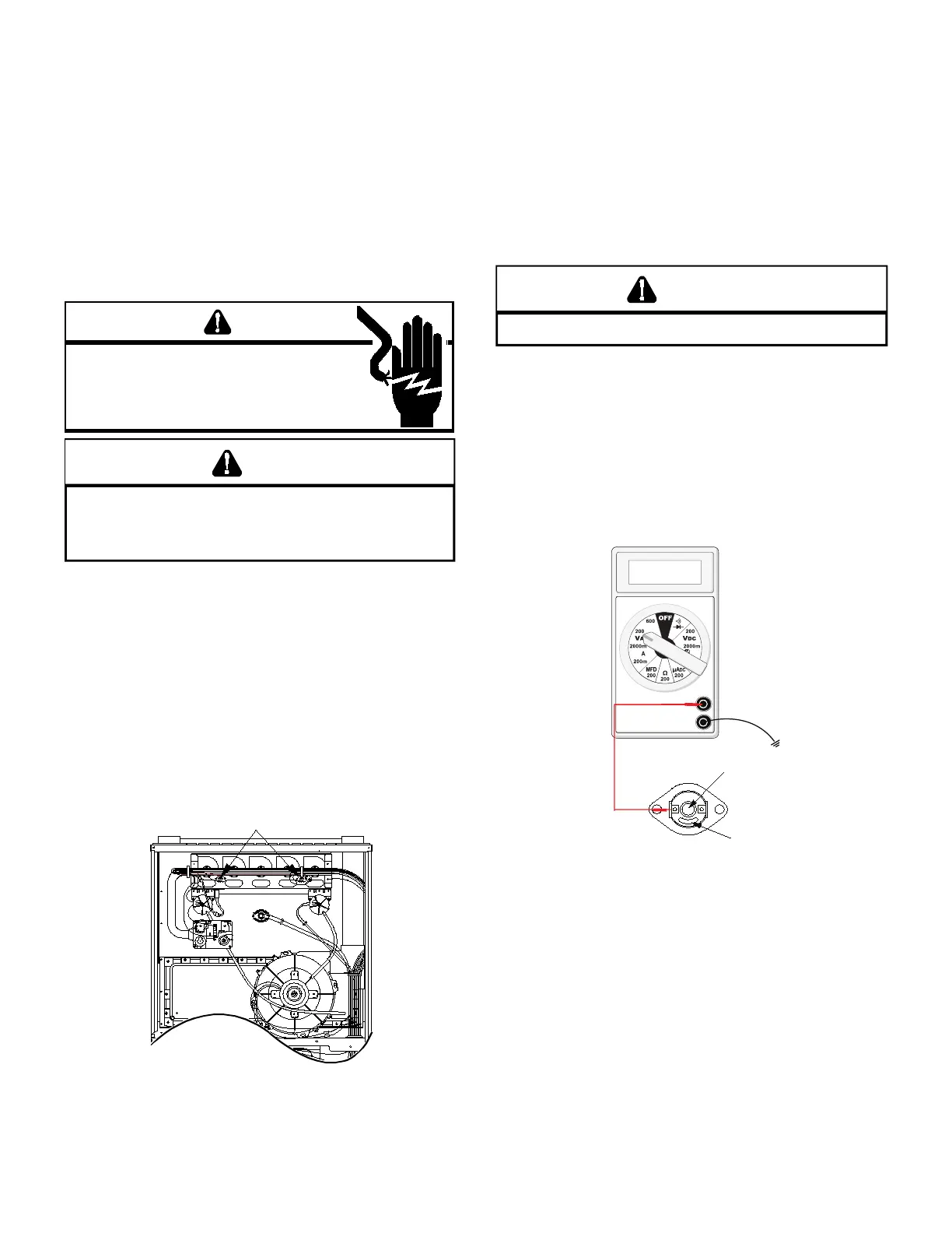
reset. The control is located in the blower compartment of
the furnace on the blower deck, as shown in the following
illustration.
WARNING
IG
VLAGE
D
ISCNNEC
ALL
PWER ERE SERVICING R
INSALLING IS NI
M
LIPLE PWER SRCES MA
E PRESEN
AILRE D S MA CASE PRPER
DAMAGE PERSNAL INJR R DEA
WARNING
AVID PSSILE IRE NL RESE E AXILIAR LIMI CNRL
NCE
I I SLD PEN A SECND IME A QALIIED SERVICER
MS DEERMINE W E AXILIAR LIMI PENED ERE
RESEING AGAIN
To aid in identifying these controls, color coded labels are
attached to the back of the controls. Refer to the Auxiliary
Limit Charts in furnace Technical Manual for color codes and
temperature settings.
A temperature activated manual reset control is mounted to
the manifold assembly on 90% furnaces, as shown in the
following illustrations.
Should read continuous unless heat exchanger temperature is
above limit control setting. If not as above, replace the control.
*
*
*
* *
*
*
2
FLAME
ROLLOUT
SWITCHES
The control is designed to open should a ame roll out oc
control opens, the air circulation blower will run continuously.
On single-stage models, the ignition control diagnostic light
will ash (6) six times indicating a trip of the rollout switch or
an open control board fuse.
To aid in iderntifying these controls, color-coded labels have
been axed to the back of these controls. Refer to the Rollout
Limit Charts in furnace Technical Manual for temperature
settings and color codes.
L
INE VLAGE NW PRESEN
WARNING
1. Remove the burner compartment door to gain access to
the rollout switch(es) mounted to burner bracket.
The servicer should reset the ignition control by opening and
closing the thermostat circuit. Then look for the ignitor glowing
which indicates there is power to the ignition control. Measure
the voltage between each side of the rollout control and
ground while the ignition control tries to power the gas valve.
2. Measure the voltage between each side of the rollout
control and ground during the ignition attempt. Refer to
the following gure.
RED
RESET
BUTTON
COLOR
IDENTIFYING
a. If no voltage is measured on either side of control it
indicates ignition control or wiring to control problem.
b. If voltage is measured on one side of the control and
not the other it indicates the control is open.
c. If voltage is measured on both sides of the control the
wiring to gas valve or valve is at fault.
3. After check and/or replacement of rollout switch, reinstall
burner compartment door and verify proper unit operation.
 Loading...