SERVICING
41
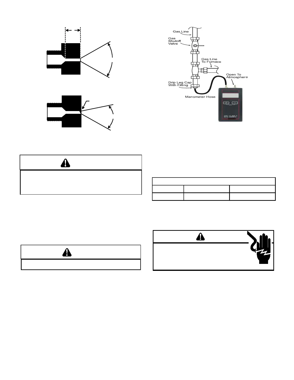
The length of Dimension “A” determines the angle of Gas
Stream “B”.
A dent or burr will cause a severe deection of the gas stream.
PREVEN NRELIALE PERAIN R EQIPMEN DAMAGE E
INLE GAS SPPL PRESSRE MS E AS SPECIIED N E NI
RAING PLAE WI ALL ER SELD GAS IRED APPLIANCES
PERAING
Gas inlet and manifold pressures should be checked and
adjusted in accordance to the type of fuel being consumed.
The line pressure supplied to the gas valve must be within the
range specied below. The supply pressure can be measured
at the gas valve inlet pressure tap or at a hose tting installed
in the gas piping drip leg. The supply pressure must be
measured with the burners operating. To measure the gas
supply pressure, use the following procedure.
WARNING
DISC
NNEC ELECRICAL PWER AND S GAS SPPL
1. After turning o gas to furnace at the manual gas shuto
valve external to the furnace, remove burner compartment
door to gain access to the gas valve.
2. Connect a calibrated water manometer (or appropriate
gas pressure gauge) at either the gas valve inlet pressure
tap or the gas piping drip leg as shown in the following
gures.
At either location, a hose tting must be installed prior
to making the hose connection.
Use adapter kit #0151K00000S to measure gas
pressure on White-Rodgers 36G22 gas valves.
3. Turn ON the gas and electrical power supply and operate
the furnace and all other gas consuming appliances on
the same gas supply line.
4. Measure furnace gas supply pressure with burners ring.
Supply pressure must be within the range specied in the
following table.
Natural Gas Minimum: 4.5" w.c. Maximum: 10.0" w.c.
Propane Gas Minimum: 11.0" w.c. Maximum: 13.0" w.c.
If supply pressure differs from above, make necessary
adjustments to pressure regulator, gas piping size, etc., and/
or consult with local gas utility.
WARNING
IG
VLAGE
D
ISCNNEC
ALL
ELECRICAL PWER AND S GAS
SPPL ERE SERVICING R INSALLING IS NI
M
LIPLE PWER SRCES MA E PRESEN
AILRE
D S MA CASE PRPER DAMAGE PERSNAL INJR R DEA
5. Disconnect manometer after turning o gas at manual
shuto valve. Reinstall plug before turning on gas to
furnace.
6. Turn OFF any unnecessary gas appliances started in step
3.
7. Turn on gas to furnace and check for leaks. If leaks are
found, repair and then reinstall burner compartment door.
8. Turn on electrical power and verify proper unit operation.
 Loading...