SERVICING
40
WARNING
IG
VLAGE
D
ISCNNEC
ALL
PWER ERE SERVICING R
INSALLING IS NI
M
LIPLE PWER SRCES MA
E PRESEN
AILRE D S MA CASE PRPER
DAMAGE PERSNAL INJR R DEA
1. Remove burner compartment door to gain access to
the induced draft blower motor.
2. Disconnect the motor wire leads from its connection
point at the induced draft motor.
3. Using a ohmmeter, test for continuity between each of
the motor leads.
4. Touch one probe of the ohmmeter to the motor frame
(ground) and the other probe in turn to each lead.
If the windings do not test continuous or a reading is
obtained to ground, replace the motor.
5. If the windings have a continuity reading, reconnect
wires. Turn power on to the furnace and turn the
thermostat on in the heating mode. Check voltage for
115V at the induced draft motor terminals during the tri-
al for ignition. If you have 115V and the motor does not
run, replace the induced draft motor.
6. After completing check and/or replacement of induced
draft motor, reinstall burner compartment door.
7. Turn on electrical power and verify proper unit opera-
tion.
A combination redundant operator type gas valve which
provides all manual and automatic control functions required
for gas red heating equipment is used.
The valve provides control of main burner gas ow, pressure
regulation, and 100 percent safety shut-o.
WARNING
DISCNNEC ALL PWER ERE SERVICING
Single stage gas valves should be tested on the furnace with
24 VAC connected to the gas valve and manometers reading
supply line and manifold pressures.
The main burners are used to provide complete combustion
of various fuels in a limited space, and transfer this heat of
the burning process to the heat exchanger.
Proper ignition, combustion, and extinction are primarily due
to burner design, orice sizing, gas pressure, primary and
secondary air, vent and proper seating of burners.
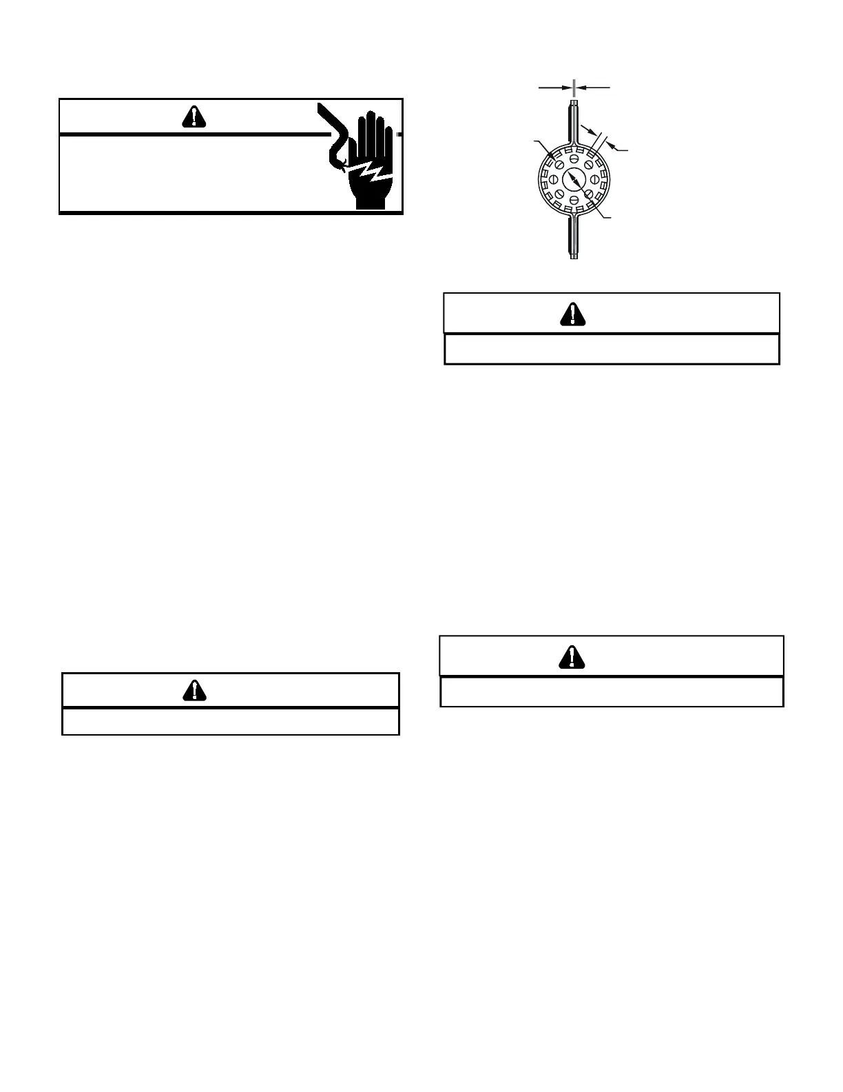
Burners have been redesigned for 34.5” chassis furnaces.
Overall length and width dimensions remain the same as 40”
model burners. The burners used 34.5” models have burner
head insert with larger diameter center hole and a larger
number of surrounding holes.
.025 .002
(CARRYOVER SLOT WIDTH)
±
16X
.125 x .030 MIN SLOT
12X Ø.125
Ø.562
WARNING
DISCNNEC ALL GAS AND ELECRICAL PWER SPPL
In checking main burners, look for signs of rust, oversized and
undersized carry over ports restricted with foreign material,
etc, refer to previous drawing. Burner cross-over slots should
not be altered in size.
Single stage furnaces are factory equipped with #45 gas
orices.
Orices should be treated with care in order to prevent
damage. They should be removed and installed with a box-
end wrench in order to prevent distortion. In no instance
should an orice be peened over and redrilled. This will
change the angle or deflection of the vacuum effect or
entraining of primary air, which will make it dicult to adjust
the ame properly.
WARNING
DISCNNEC ALL GAS AND ELECRICAL PWER SPPL
1. Check orice visually for distortion and/or burrs.
2. Check orice size with orice sizing drills.
3. If resizing is required, a new orice of the same physical
size and angle with proper drill size opening should be
installed.
 Loading...