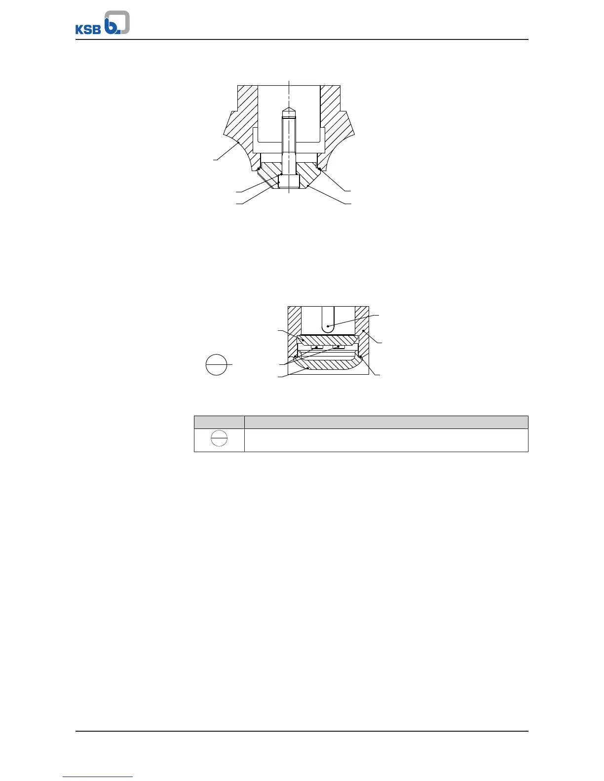
Fig.49: Impeller fastening elements N110-3
1. Insert keys 940.01.
2. Fit impeller 230 using a special impeller fitting and removal tool.
3. Fit impeller hub cap 260.01 with O-ring 412.55 and O-ring 412.06.
4. Screw in hexagon socket head cap screw 914.10 (right-hand thread).
Impeller fastening elements N140, N160
Fig.50: Impeller fastening elements N140, N160
Table45: Key to the symbols and codes
Symbol Description
Always secure screwed connections marked with this symbol with
Loctite 243.
1. Insert keys 940.01.
2. Fit impeller 230 using a special impeller fitting and removal tool.
3. Screw in hexagon socket head cap screws 914.87 with disc 550.87. Secure the
hexagon socket head cap screws with a thread-locking agent (Loctite, type243).
4. Insert O-ring 412.06.
5. Screw in impeller hub cap 260.01 using a special wrench (right-hand thread).
7.5.2.2.1 Fitting the impeller using the special impeller fitting and removal tool
1. Fit the impeller using the special impeller fitting and removal tool.
(ðSection,Page83)
2. Fit the impeller fastening elements.


 To Next Page