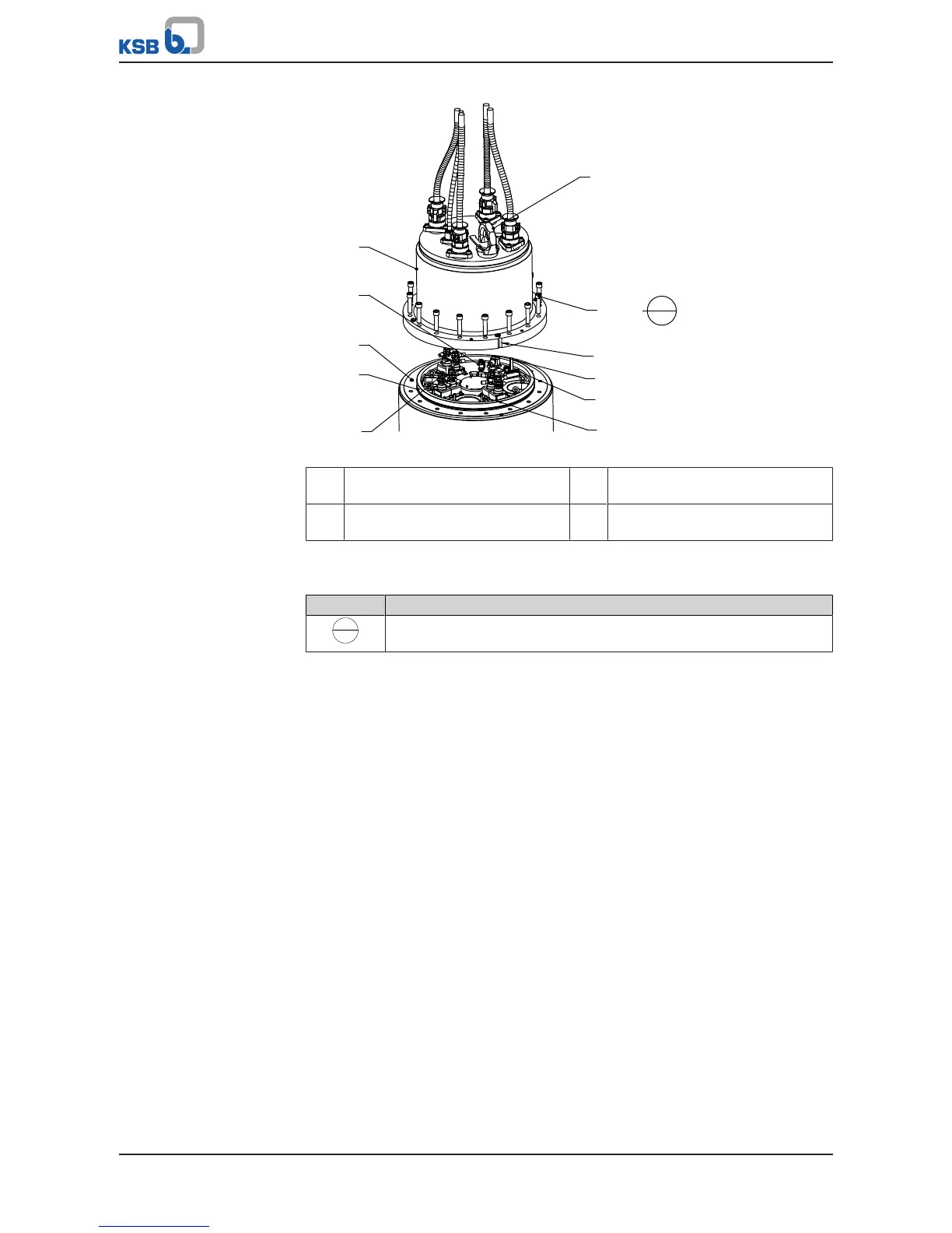
Fig.53: Fitting the motor housing cover
a Alignment groove on motor
housing cover
b Alignment groove on bearing
bracket
c Anti-rotation device on bearing
bracket
**: Optional
Table47: Key to the symbols and codes
Symbol Description
Always secure screwed connections marked with this symbol with
Loctite 243.
ü A new O-ring has been inserted into the groove of bearing bracket 330.
1. Attach lifting equipment to eyebolt 900.04 or bail 571 of motor housing cover
812. Lift up the motor housing cover and lower it down onto motor housing 811
until only a gap remains which allows work to continue. Make sure that the
alignment grooves on the motor housing and on the bearing bracket are
correctly aligned. Only in this position will the anti-rotation device on the
bearing bracket engage in the corresponding recess in the motor housing cover.
2. Connect the control cable properly to the terminals at the plug. Then plug it
into connector block 81-2.01 (and 81-2.03, depending on the model) which is
fastened to bearing bracket 330.
3. Fasten the power cable ends with cable terminal to terminal 185, using disc
550.23 and nuts.
4. Tie the control cable and power cables together with cable ties.
5. Carry out electrical tests of the cables and monitoring equipment.
6. If the test results are successful, slowly lower motor housing cover 812 onto
motor housing 811.
Watch the alignment grooves in motor housing cover 812 and motor housing
811. The grooves must be aligned correctly.
7. Fasten motor housing cover 812 to motor housing 811 or motor unit 80-1 with
hexagon socket head cap screws 914.01. Secure the screwed connection with
Loctite 243.
Observe the tightening torque!
8. Cover the jacking threads with caps 903.51.
9. Perform a leak test on the motor.


 To Next Page