21
Copyright 2018 by Amber Kinetics. All rights reserved.
3 - INSTALLATION
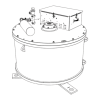
3. Remove the six (6) bolts securing the lower
Bearing Cap using a 3/8” (9.5mm) Allen wrench.
Figure 8: Bolts securing the lower Bearing Cap
4. Place the lower Bearing Cap inside a clean plastic
bag or other storage.
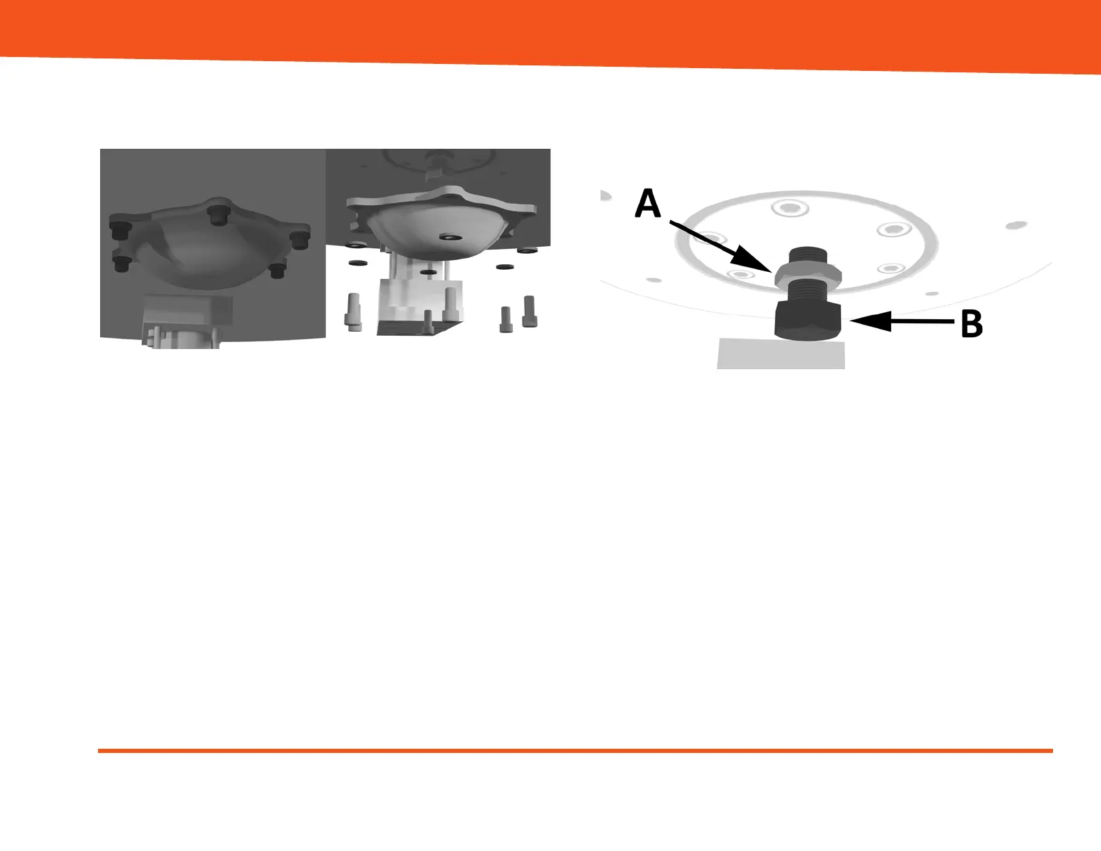
5. Loosen the locknut (A) securing the jack screw (B)
to the M32 flywheel using the 1.5” (~39mm) open-
ended wrench.
Figure 9: Locknut (A) and jack screw (B)
6. Using the socket torque wrench with a 1.5”
(~39mm) socket, turn the jack screw (B) clockwise
until the Handheld Load Cell Reader indicates
125lbs (+/- 10lbs).
7. Turn the jack screw (B) counterclockwise 220
degrees (+/- 10 degrees).
8. Record the load displayed on the Handheld Load
Cell Reader. The reading should be between 0 and
25 lbs.