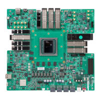
PMC and LPD MIO
The following secons provide the MIO peripheral mapping implemented on the VPK180
evaluaon board. See the Versal ACAP Technical Reference Manual (AM011) for more informaon
on MIO peripheral mapping. Addional signal connecvity can be located in the following
schemac secons:
• Bank 500: See schemac page 20
• Bank 501: See schemac page 21
• Bank 502: See schemac page 21
The following table provides MIO peripheral mapping implemented on the VPK180 evaluaon
board. The ACAP bank 500, 501, and 502 mappings are listed in the following table.
Chapter 3: Board Component Descriptions
UG1582 (v1.0) February 21, 2023 www.xilinx.com
VPK180 Board User Guide 29