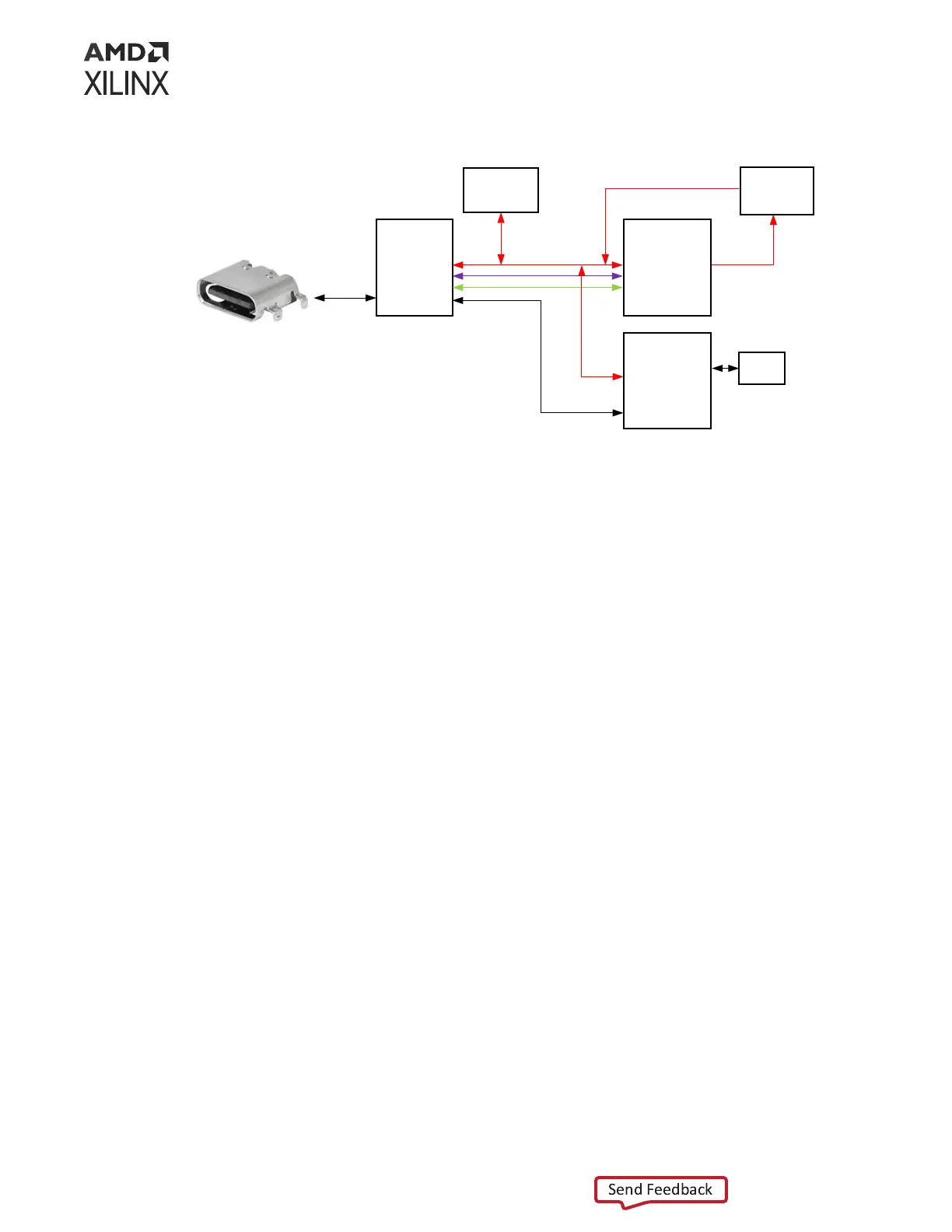
Figure 12: FT4232HL UART Connections
FTDI
PortA
PortB
PortC
PortD
XCVP1802
ACAP
TDO
GTY
HSDP
PS UART
PL UART
ZU4
MPSoC
PS UART
PC4
HDR
PC4
HDR
USB2.0
SysCon UART
Versal PL UART
Versal PS UART
JTAG
J369
12401598E4#2A
TDI
FMC+
Versal JTAG TDI/TDO
X26551-102722
For more informaon on the FT4232HL, see the Future Technology Devices Internaonal Ltd.
website.
Note: This FTDI conguraon image is not provided nor supported. To replicate this feature, a JTAG-SMT2
from Digilent or similar is recommended.
The detailed ACAP connecons for the feature described in this secon are documented in the
VPK180 board XDC le, referenced in Appendix B: Xilinx Design Constraints.
PMC MIO[44:45] I2C1 Bus
[Figure 3, callout 12]
Bus I2C1 connects the XCVP1802 U1 PS bank 501 and the XCZU4EG system controller U125
PS bank 501 to two I2C switches (TCA9548A U35 and U322). These I2C1 connecons enable
I2C communicaons with other I2C capable target devices. TCA9548A U35 is pin-strapped to
respond to I2C address 0x74. TCA9548A U322 is pin-strapped to respond to I2C address 0x75.
The following gure shows the I2C1 bus connecvity detailed in the table below.
Details for controlling the U35 and U322 TCA9548A switches are available in the data sheet on
the Texas Instruments website.
The detailed ACAP connecons for the feature described in this secon are documented in the
VPK180 evaluaon board XDC le, referenced in Appendix B: Xilinx Design Constraints.
Chapter 3: Board Component Descriptions
UG1582 (v1.0) February 21, 2023 www.xilinx.com
VPK180 Board User Guide 38