60 18-09-2007 122770 06
When connecting new Main PCB’s to old Power PCB’s they must be
connected with a cable 125232.
Power PCB
ATC-125
There is no DIP-Switch on the power PCB for the ATC-125 and the
Power PCB has no need for any further adjusting or configuration.
New Power PCB with new Main PCB
When version 2 Power PCBs are connected to version 2 Main PCBs,
the DIP-Switch Settings on the Power PCBs are as follows:
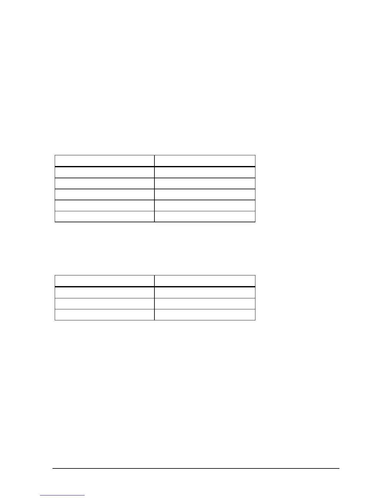
Model DIP-Switch Setting
ATC-140 00010101
ATC-155/156/157 01000100
ATC-250 00010100
ATC-320 * 00000000
ATC-650 01000000
New Power PCB with old Main PCB
When version 2 Power PCB’s are connected to version 1 Main
PCB’s, the DIP-Switch Settings on the Power PCB’s are as follows:
Model DIP-Switch Setting
ATC-155/156/157 10001110
ATC-320* 00001010
ATC-650 10001010
When connecting new Power PCB’s with old Main PCB’s they must
be connected with a cable 125231.
* See section 2.3.3 for configuring the Power PCB, version 2.
2.3.2 Configuring the Power PCB for ATC-320 A/B
(version 1)
Remove the diode D14 from the Power PCB.
 Loading...