EasyManuals Logo

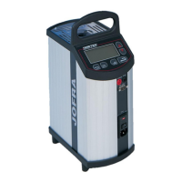
Ametek JOFRA ATC-125 Service Manual

Ametek JOFRA ATC-125
89 pages
To Previous Page IconTo Previous Page
Page #89 background imageLoading...
Page #89 background image
122770 06 18-09-2007 89
3.18 Wiring Diagram – ATC-250/320/650 B
2
Main
Board
Power
Board
Display
Controller Board
Display Keyboard
RS232
Board
Fan
Well
Trafo
34
CN7
CN6 CN8
CN3
34
16
CN2
CN4
Sync.
CN3
RS232
30
CN4
CN2
CN3 CN5 CN1
12 2 9
2
CN3
CN4 CN1
CN8
CN7
CN2
2
2
8
Pt100
4
Heating elements
Blue
Orange
Grey
Brown
A
B
C
D
Mains input
including
fuses and
voltage
selector
GND
12299501
6
4
4
Secondary
Primary
4
Resistor Resistor
2
4
Temperature
protection TC
CN9
CN6
CN5
2
2
Differential TC
Input
Board
TC
Connector
Ref.
CN16 CN15
CN1
R1CN6
CN9
CN7
SWTEST (+)
CN8
SWTEST (-)
CN10
+24V
CN11
mA (+)
CN12
GND
CN13
V (+)
CN5
RTD (I+)
CN4
RTD (S+)
CN3
RTD (S-)
CN2
RTD (I-)
CN14
EARTH
2
2
4
Display
Power
CN11
Motor
Only ATC-250 B

Other manuals for Ametek JOFRA ATC-125

Questions and Answers:

Question and Answer IconNeed help?

Do you have a question about the Ametek JOFRA ATC-125 and is the answer not in the manual?

Ametek JOFRA ATC-125 Specifications

General IconGeneral
BrandAmetek
ModelJOFRA ATC-125
CategoryMeasuring Instruments
LanguageEnglish

Related product manuals