122770 06 18-09-2007 61
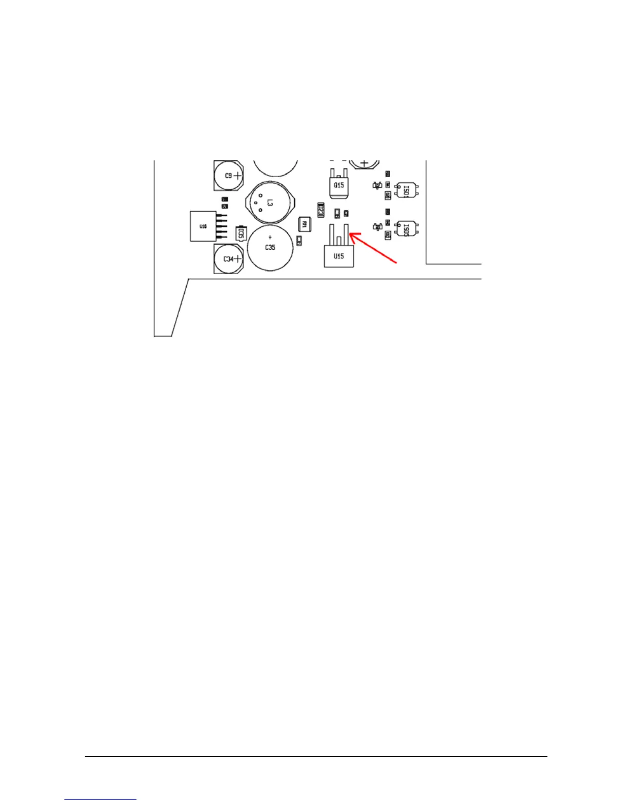
2.3.3 Configuring the Power PCB for ATC-320 A/B
(version 2)
When setting up a ATC-320 A or B with version 2 Power PCB, one
terminal on U15 must be disconected. See drawing below.
2.3.4 Configuring the Power PCB for ATC-650 A/B
(version 1)
Remove the resistor R20 from the Power PCB.
2.4 Adjusting and Testing PCB’s
2.4.1 Current limiter for ATC-140/155/156/157 A/B
Necessary equipment
Voltmeter 0-1V with an accuracy of 0.01V.
Set-up
Voltmeter.
 Loading...