User Guide
Landcal Blackbody Source
Type R1500T
Page 7
5 Commissioning
5.1 Inspection on receipt
Physically examine all items for any damage that may have occurred during
transit. Check the contents against the packing note.
If any items have been damaged in transit, this should be reported to the carrier
and to the supplier immediately, BUT DO NOT RETURN damaged items until the
carrier has considered a claim. Save the packing with the damaged article for
inspection by the carrier.
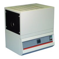
5.2 Furnace assembly
The following paragraphs describe the step by step procedure to prepare the
furnace for switch on. See also Fig. 3.
Place the furnace in a well ventilated room on a surface which is resistant to
heat. Ensure that there is free space around the furnace. Do not obstruct any
of the vents in the control section, they are needed to keep the controls cool.
To minimise the risk of damage to the furnace during transit, the target cavity
together with a ceramic plug, six silicon carbide heating elements and a set of
element support brackets/braids are supplied separately. These items should be
tted as follows:
1) Remove the stainless steel front panel unscrewing the four equally spaced
screws. The ceramic tube in the back of the furnace chamber supports the
smaller end of the cavity.
2) Insert the cavity into the furnace so that the front edge of the cavity is
level with the second layer of insulation.
3) Gently push the ceramic plug into the insulation to hold the target in place.
4) Replace the stainless steel plate.
5) Remove the four screws that hold the painted rear panel to gain access to
the element connections.
6) Carefully insert the elements into the furnace ensuring that they locate into
the recess at the front. Extreme care should be taken not to strain the
elements as they are very fragile.
7) Position the element support brackets to locate onto the element heads and
use the self-tapping screws to attach the brackets to the brickbox. Tighten
rmly into position.
8) Attach the electrical connections as shown in Fig. 4 (220/240V) or Fig. 5
(110/220V).
9) Replace the back panel.
10) Connect the furnace to the mains supply as described in ‘Section 4.0 -
Electrical Supply’.
 Loading...