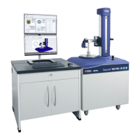
Do you have a question about the Ametek TAYLOR HOBSON TALYROND 500 PRO and is the answer not in the manual?
| Max Component Weight | 50 kg |
|---|---|
| Measurement Range | ±1 mm |
| Probe Type | Inductive |
| Data Output | USB |
| Software Compatibility | Talyprofile |
| Power Supply | 110/240 VAC, 50/60 Hz |
Detailed explanation of the Instrument view within Metrology 4.0.
Explanation of icons and functions within the instrument ribbon.
Controls for setting the horizontal orientation of the stylus.
Controls for setting the vertical orientation of the stylus.
Moving axes by clicking and holding an icon.
Moving axes to specific absolute coordinates.
Moving axes by a defined distance.
Operation of the vacuum chuck feature.
Using the carousel for multi-part measurements.
Description of the UHPR stage for high-precision roundness.
Setting independent speeds for each axis.
Inputting target positions for axes.
Inputting distances for axis movement.
Resetting axis positions to default or current values.
Starting a new measurement program.
Loading an existing measurement program.
Modifying an existing measurement program.
Preventing further editing of a program.
Editing the program's text file.
Saving measurement programs.
Viewing and defining program properties.
Different methods to execute measurement programs.
Halting a running measurement program.
Recording program steps.
Handling errors during program execution.
Testing programs at slower speeds.
Performing roundness measurements.
Performing flatness measurements.
Measuring profiles in the Z-axis.
Measuring profiles in the X-axis.
Measuring and mapping cylindrical surfaces.
Performing high-precision roundness measurements.
Locking or unlocking the system.
Logging out of the software.
Modifying user passwords.
Managing user accounts.
Assigning roles to users.
Configuring instrument settings.
Applying system corrections.
Managing software licenses.
Choosing the software language.
Generating service reports.
Main tool for configuring the instrument.
Managing calibration artefacts.
Setting home positions for axes.
Defining and calibrating axis reference points.
Applying datum corrections to axes.
Setting the spindle's offset angle.
Adjusting device performance parameters.
Managing installed styli.
Setting axis travel limits.
Correcting spindle closing errors.
Icon to halt instrument activity.
Icon to move the instrument to a parked position.
Icons indicating successful or missing calibration.
Loading and saving workspace layouts.
Saving and loading user profiles.
Importing/exporting part data and settings.
Accessing help documentation and license details.
Status of Centre & Level homing.
Information about the Metrology 4.0 software.
Dialog box for configuring gauge settings including stylus.
Procedure for calibrating the scale and crutch angle.
Dialog box for flick standard calibration.
Dialog box for slip block calibration.
Dialog box for ball calibration.
Dialog box for 3-line standard calibration.
Selecting gauge ranges for calibration.
Setting the valid duration for calibration.
Setting the crutch angle during calibration.
Selecting the calibration artefact.
Selecting the stylus for calibration.
Setting speed and direction for calibration.
Indicating the measurement axis.
Calibration for small shank styli.
Setting the measurement length for calibration.
Description of the flick standard artefact.
Description of slip blocks artefacts.
Description of the ball standard artefact.
Description of the 3-line standard artefact.
Steps to add a new calibration artefact.
Steps to edit an existing calibration artefact.
Steps to remove a calibration artefact.
Procedure for taking a roundness measurement.
Performing 2D measurements along the Z-axis.
Performing 2D measurements along the X-axis.
Naming measurements for identification.
Option to keep measurement results visible.
Automatically displaying analysis after measurement.
Prompting for user input before measurement.
Selecting the gauge range for measurement.
Setting speed and direction for measurement.
Configuring measurement types like multiplane and HPR.
Options for applying, appending, or replacing analysis results.
Tracking surface with X-axis during measurement.
Ensuring correct gauge reading before starting.
Setting clearance after measurement completion.
Selecting the starting position for measurement.
Setting the measurement length.
Returning stylus to start position.
Rotational separation for vertical traces.
Number of vertical traces to measure.
Speed for moving to the next trace.
Direction of movement between traces.
Speed for Z-axis movement back to start.
Analyzing surface results in degrees.
Setting radius for arc length calculation.
Settings for the rotary stage.
Accepted closing error value for measurements.
Number of retries for closing error.
Options for displaying results in analysis.
Path for exporting measurement data.