4.2 Op er a tion
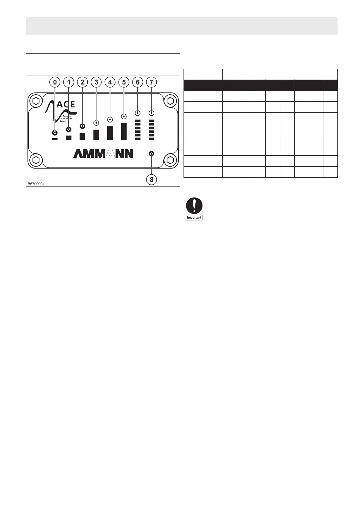
The var i ous op er at ing sta tuses are shown on the con trol panel
as fol lows:
•
The sys tem starts au to mat i cally when the ma chine is started.
Next, the sys tem initializes:
- The sta tus LED (8) blinks; the LEDs (0-7) light up in a row
from 0 to 7 and then go back off.
•
Af ter suc cess ful ini tial iza tion, the sta tus LED (8) glows. The
sys tem is now ready to op er ate.
•
The rel a tive com pres sion value is shown by the LEDs as fol -
lows. The num ber of glow ing LEDs sym bol i cally rep re sents
the in creas ing soil com pres sion.
LED
VG
0 1 2 3 4 5 6 7
0 – 19 %
l
20 – 40 %
l l
41 – 60 %
l l l
61 – 80 %
l l l l
81 – 100 %
l l l l l
101 – 120 %
l l l l l l
121 – 140 %
l l l l l l l
141 – 150 %
l l l l l l l l
l – red
VG – De gree of com pres sion
•
If the sta tus LED glows, and the 0 LED blinks, the vi bra tion fre -
quency is to high or too low. No mea sure ment value can be
cal cu lated.
•
If the 0 LED glows, and the sta tus LED gives off a blink sig nal,
the mea sur ing sys tem is mal func tion ing. In this case, con tact
Ammann ser vice.
1)
Op tio nal equip ment
LM22020000-2 HbmG gnu thci dreV nna mmA 8102/20
Cor rect mea sure ment val ues can only be achieved by
driv ing for ward and back wards at max i mum speed.
4. ACEe con sys tem
51