This document outlines the assembly instructions for the Amphenol 2-position HV Flange Connector, specifically the HVB321(X)-XX series. This connector is designed for high-voltage applications and requires careful assembly to ensure proper function and safety. The manual provides a step-by-step guide, including detailed illustrations and technical specifications, to facilitate correct installation.
Function Description:
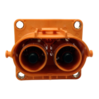
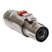
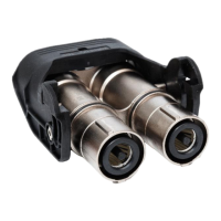
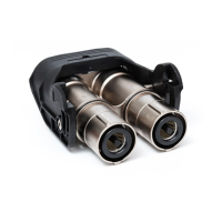
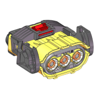
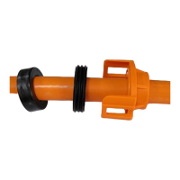
The Amphenol HV Flange Connector is a robust, two-position connector designed for high-voltage power transmission. It is intended for use in applications requiring reliable and secure electrical connections, particularly where a flange mounting is necessary. The connector's design incorporates features to ensure electrical insulation, shielding, and mechanical integrity, crucial for high-voltage environments. It accommodates various cable sizes, making it versatile for different power requirements. The assembly process emphasizes proper cable preparation, shielding termination, and secure crimping to achieve optimal performance and safety.
Important Technical Specifications:
The connector supports a range of cable sizes, with specific dimensions and crimping parameters provided for each.
-
Cable Sizes (mm²):
-
Recommended Cable Dimensions (for 35mm² cable):
- Insulation OD: 10.0±0.4
- Jacket OD: 14.1±0.4
- Recommended width of the terminal: ≤16.5mm
-
Recommended Cable Dimensions (for 50mm² cable):
- Insulation OD: 12.5±0.4
- Jacket OD: 17.1±0.5
- Recommended width of the terminal: ≤18.5mm
-
Recommended Cable Dimensions (for 70mm² cable):
- Insulation OD: 14.5±0.4
- Jacket OD: 19.1±0.5
- Recommended width of the terminal: ≤18.5mm (AC-CP001460)
-
Stripping Lengths:
- Insulation Strip Length "A": According to terminal of customer
- Jacket Strip Length "B": L+12mm (where L is the insulation strip length)
- Braiding Wire Treat: Trim and keep the braiding wire to 14±1mm.
-
Crimping Specifications:
- The braiding should not exceed 1mm from the pressure ring after crimping.
- The pull force after crimping the pressure ring must be greater than 150N.
- Recommended crimping height for the terminal is 80-90% of the conductor compression ratio.
- Hexagonal crimping is specified for the pressure ring.
-
Flange Screw Assembly Torque: 6.2-7.6 N.m.
-
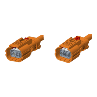
Keying Options:
- X Key: For 35mm², 50mm², 70mm² cables.
- Y Key: For 35mm², 50mm², 70mm² cables.
These keying options likely ensure correct mating and prevent misconnection.
Usage Features:
The assembly process is designed to be systematic, ensuring a secure and reliable connection. Key usage features include:
- Cable Preparation: The first step involves precise stripping of the cable jacket and insulation, followed by folding back the braiding wire. This meticulous preparation is critical for effective shielding and insulation.
- Component Insertion: Various accessories, including the cushion ring, rear sealing ring, and end cap, are inserted onto the cable in a specific order. These components contribute to the connector's environmental sealing and mechanical protection.
- Shielding Termination: A crucial step involves placing and crimping a pressure ring onto the braiding. This ensures proper grounding and shielding effectiveness. The crimping process requires a mold-free machine and adherence to specific pull force and crimping height requirements to guarantee a robust connection that will not shift.
- Terminal Crimping: The terminal is crimped according to the customer's specifications, with a recommended conductor compression ratio of 80-90%. This ensures optimal electrical contact and current carrying capacity.
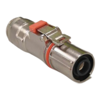
- Shielded Ring Assembly: A shielded ring is assembled onto the front end of the pressure ring, and the cable is inserted into the main body of the PIN B connector. This step integrates the shielding into the connector housing.
- Sealing and Mechanical Fastening: The cushion ring, rear sealing ring, and end cap are successively tightened onto the wire and into the HV metal shell, providing environmental protection and mechanical stability. The end cap features buckles on both sides that must be securely in place.
- Repeatability: The assembly steps for PIN A are identical to those for PIN B, ensuring consistency and ease of assembly for both poles of the connector.
- Front Sealing Rings: Two front sealing rings are inserted onto the connector head, providing an additional layer of environmental sealing at the mating interface.
- Flange Mounting: The connector is designed for flange mounting, with a recommended screw assembly torque of 6.2-7.6 N.m, ensuring a secure attachment to the application's housing.
Maintenance Features:
While the document primarily focuses on assembly, the design inherently supports long-term reliability, minimizing the need for frequent maintenance.
- Robust Construction: The use of high-quality materials and precise assembly procedures ensures a durable connection that can withstand environmental stresses and operational demands.
- Effective Sealing: Multiple sealing rings (cushion ring, rear sealing ring, front sealing rings) protect the internal components from moisture, dust, and other contaminants, extending the connector's lifespan and reducing the likelihood of performance degradation.
- Secure Crimping: The specified crimping parameters and pull force requirements ensure that the electrical connections are mechanically sound and resistant to vibration and thermal cycling, which are common causes of failure in less robust connectors.
- Shielding Integrity: The detailed instructions for braiding termination and shielded ring assembly maintain the connector's electromagnetic compatibility (EMC) performance, crucial for preventing interference in sensitive electronic systems.
- Standardized Design: As part of the standard HV Flange series, the connector benefits from established design principles and testing protocols, contributing to its overall reliability and ease of integration into existing systems.
- Clear Documentation: The comprehensive assembly manual, with its detailed steps and illustrations, serves as a valuable resource for ensuring correct installation, which is the foundation for long-term, trouble-free operation. Proper initial assembly significantly reduces the need for subsequent maintenance.
This Amphenol HV Flange Connector is a critical component for high-voltage applications, designed with an emphasis on safety, reliability, and ease of assembly, ensuring robust performance in demanding environments.