EasyManua.ls Logo

Amtrol BOILERMATE WH Series User Manual

Amtrol BOILERMATE WH Series
12 pages
To Next Page IconTo Next Page
Page #1 background imageLoading...
Page #1 background image
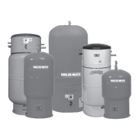
BOILERMATE
®
INDIRECT-FIRED WATER HEATERS
INSTALLATION & OPERATION INSTRUCTIONS
NOTE: A properly sized thermal
expansion tank is required and should
be installed in accordance with the
product installation manual.
NOTE: The thermostat is adjusted to
120°F when shipped from the factory.
READ CAREFULLY THE PRODUCT
INSTALLATION & OPERATION INSTRUCTIONS.
FAILURE TO FOLLOW THE INSTRUCTIONS AND WARNINGS IN THE
MANUAL MAY RESULT IN SERIOUS OR FATAL INJURY AND/OR
PROPERTY DAMAGE, AND WILL VOID THE PRODUCT WARRANTY.
THIS PRODUCT MUST BE INSTALLED BY A QUALIFIED
PROFESSIONAL. FOLLOW ALL APPLICABLE LOCAL AND STATE
CODES AND REGULATIONS, IN THE ABSENCE OF SUCH CODES,
FOLLOW THE CURRENT EDITIONS OF THE NATIONAL PLUMBING
CODE AND NATIONAL ELECTRIC CODE, AS APPLICABLE.
This Product, like most Products under pressure,
may over time corrode, weaken and burst or
explode, causing serious or fatal injury, leaking or flooding and/or property
damage. To minimize risk, a licensed professional must install and
periodically inspect and service the Product. A drip pan connected to an
adequate drain must be installed if leaking or flooding could cause property
damage. Do not locate in an area where leaking could cause property
damage to the area adjacent to the appliance or to lower floors of
the structure.
CALIFORNIA PROPOSITION 65 WARNING! This product contains a
chemical known by the State of California to cause cancer and to cause
birth defects or other reproductive harm. (California Installer/Contractor -
California law requires that this notice be given to consumer/end user of
this product.) For more information: www.amtrol.com/prop65.html
A relief valve must be installed to prevent pressure in
excess of local code requirement or maximum
working pressure designated in the Product Manual, whichever is less. At
least once every 3 years or if discharge is present, a licensed contractor
should inspect the temperature and pressure relief valve and replace if
corrosion is evident or the valve does not function.
FAILURE TO INSPECT THIS VALVE AS DIRECTED COULD RESULT
IN UNSAFE TEMPERATURE OR PRESSURE BUILD-UP WHICH
CAN RESULT IN PRODUCT FAILURE, SERIOUS INJURY OR
DEATH AND/OR SEVERE PROPERTY DAMAGE AND VOID THE
PRODUCT WARRANTY.
Chlorine Aggressive Water: The water quality can
significantly influence the life of this Product. You
should test for corrosive elements, acidity, total solids and other relevant
contaminants, including chlorine and treat your water appropriately to
insure satisfactory performance and prevent premature failure.
EXPLOSION HAZARD. The pressure of the heat
transfer medium must be limited to a maximum of 30
psig by an approved safety or relief valve on your boiler. The water heater
pressure must be limited to 150 psig maximum by the installation of a
temperature and pressure relief valve (included). The relief tube must be
plumbed to a suitable drain per code. No reducing coupling or other
restriction may be placed in this line.
The heat transfer medium must be water or other
nontoxic fluid having a toxicity rating or class of 1, as
listed in Clinical Toxicology of Commercial Products, 5th edition. The
pressure of the heat transfer medium must be limited to 30 PSIG by an
approved safety or relief valve.
Do not expose Product to freezing temperatures or
temperatures in excess of the maximum rated
operating temperature.
NOTE: Inspect for shipping damage and notify freight carrier or store where purchased immediately if damage is present. To avoid risk of personal
injury and property damage, if the product appears to be malfunctioning or shows signs of corrosion, call a qualified professional immediately. Current
copies of the Product manual can be viewed at www.amtrol.com. Use proper safety equipment when installing.
THIS IS THE SAFETY ALERT SYMBOL. IT IS USED TO ALERT YOU TO POTENTIAL PERSONAL INJURY AND OTHER
HAZARDS. OBEY ALL SAFETY MESSAGES THAT FOLLOW THIS SYMBOL TO REDUCE THE RISK OF PERSONAL
INJURY AS WELL AS PROPERTY DAMAGE.
Models WH (Mechanical Control & Digital Control)
Models CH (Mechanical Control)
Question and Answer IconNeed help?

Do you have a question about the Amtrol BOILERMATE WH Series and is the answer not in the manual?

Amtrol BOILERMATE WH Series Specifications

General IconGeneral
BrandAmtrol
ModelBOILERMATE WH Series
CategoryWater Heater
LanguageEnglish

Summary

General Safety Information and Warnings

Safety Alert Symbol

Alerts to potential personal injury and hazards associated with the product.

Installation & Operation Warning

Emphasizes consequences of not following instructions, including injury and voided warranty.

Professional Installation Requirement

Mandates installation by a qualified professional, adhering to all applicable codes.

Product Hazard Identification

Warns of potential product failure modes like corrosion, weakening, bursting, or explosion.

California Proposition 65 Compliance

Notifies about chemicals known to cause cancer or reproductive harm.

Pressure Relief Valve Mandate

States the necessity of installing a relief valve to prevent overpressure.

Water Quality Impact

Advises on testing water for corrosive elements, especially chlorine, which affects product life.

Explosion Risk Factors

Details explosion hazards related to heat transfer medium and water pressure limits.

Heat Transfer Medium Specification

Specifies approved fluids for the heat transfer medium and their pressure limits.

Temperature Extremes Warning

Caution against exposing the product to freezing or excessively high temperatures.

Specific Safety Precautions and Hazards

Scalding Hazard Warning

Warns that water temperatures above 120°F can cause severe scalding and injury.

Thermostat and Installation Safety

Highlights risks from improper thermostat function or installation leading to scalding.

Replacement Parts Integrity

Stresses the importance of using correct replacement parts for product safety.

Space Heating Interruption Risk

Notes potential delays in space heating or freezing risks in priority modes.

Expansion Tank System Requirements

Advises on replacing hydropneumatic tanks and requiring expansion tanks for city water.

Internal Tankless Coil Safety

Warns against plugging internal tankless coil taps to prevent pressure build-up.

Electrical Safety Standards

Mandates electrical grounding according to national and local codes.

Boiler Safety Device Installation

Requires low-water cut-off or pressure reducing valve on the boiler.

Heating Zone Configuration

Specifies the unit must be installed as a separate heating zone.

Draining Procedure Hazards

Outlines dangers associated with improper draining procedures.

Bacteria Growth and Disinfection

Advises on potential bacteria growth and professional disinfection methods.

Glycol Usage Restrictions

Permits glycol use only in double-walled models due to its toxicity.

Domestic Supply Contamination Risk

Warns against connecting domestic supply to baseboard heating units to prevent contamination.

Tank Shell Integrity Warning

Prohibits drilling or penetrating the exterior tank shell.

Pre-Installation and System Design

Licensed Professional Installation

Reinforces the need for installation by licensed professionals adhering to all codes.

Drip Pan and Drainage

Requires a properly drained drip pan if leakage could cause damage.

Water Quality Assessment

Advises testing water for corrosiveness, acidity, and contaminants.

Wiring System Options

Explains Non-Priority and Priority system wiring for space heating control.

Circulator vs. Zone Valve Choice

Discusses selecting a separate circulator or a zone valve for flow control.

Boiler System Safety Components

Mandates low-water cut-off or automatic fill valve for boiler systems.

Vacuum Breaker Installation

Specifies installing a vacuum breaker to prevent damage during draining.

Required Components Overview

Lists essential components needed for WH and CH series installations.

Heat Exchanger Pressure Drop Chart

Provides a chart to determine appropriate circulator selection based on pressure drop.

Domestic Water Piping Installation

Water Supply Connections

Details connecting cold water supply and hot water piping to the unit.

Leak Detection and Repair

Outlines the process of checking for leaks after initial water supply connection.

Relief Valve and Blowdown Tube

Instructions for installing the temperature & pressure relief valve and blowdown tube.

Clearance Requirements

Specifies minimum clearances from combustible surfaces for safety.

Servicing Access Clearances

Details necessary clearances for performing maintenance and servicing.

CH Model Piping Diagrams

Illustrates recommended piping configurations for CH models.

WH Model Piping Diagrams

Illustrates recommended piping configurations for WH models.

Model-Specific Piping Schematics

Shows piping for Single Wall (CH-41Z/CH-80Z) and Double Wall (CH-41ZDW/CH-80ZDW) models.

Boiler Piping and Mechanical Control Wiring

Boiler Loop Piping

Instructions for connecting the circulator or zone valve to the boiler supply and return.

Return Line Connection Caution

Warns against connecting the return line to the suction side of heating circulators.

Flow Check Valve Installation

Advises on installing a weighted flow check on the boiler return line.

Boiler Loop Pressurization and Leak Check

Details pressurizing the boiler loop and checking for leaks.

High-Pressure Boiler Hazard

Prohibits installation on high-pressure steam boilers exceeding 15 psig.

Mechanical Aquastat Wiring Diagrams

Provides wiring diagrams for various mechanical aquastat applications.

Zone Valve Wiring Configurations

Shows wiring diagrams for 3-wire and 4-wire zone valve setups.

Other Mechanical Control Applications

Illustrates wiring for multi-zone controls and boiler control inputs.

Digital Control Wiring Diagrams

Digital Control Operating Parameters

Specifies ambient temperature, humidity, and load ratings for control installation.

Wiring Protection Requirements

Outlines requirements for protecting line-voltage and safety-circuit wiring.

Conductor Strain Relief

Notes the need for strain relief for conductors exiting enclosures.

Oil Burner Control Wiring

Wiring diagrams for oil burner controls including ZR input and high limit.

Gas Valve Control Wiring

Wiring diagrams for gas valve controls like 24 Volt, Millivolt, and Self-Generating.

Digital Control Application Wiring

Illustrates wiring for multi-zone, outdoor reset, and 4-wire zone valve applications.

Digital Control Setup and Settings

Temperature Sensor Installation

Instructions for plugging the temperature sensor into the digital control.

Zone Valve Sensor Offset Explanation

Explains the function of the zone valve sensor offset for accurate temperature readings.

Temperature Setting Safety

Warns that settings above 120°F pose a scald hazard.

Navigating Control Settings

Describes how to adjust settings using the SET, Up, and Down buttons.

Digital Control Parameter Configuration

Details adjustable settings such as Temperature, Differential, Post-Purge, and Priority.

Diagnostic Error Code Interpretation

Explains error codes (Erl, Er2, Er3) and their potential causes and solutions.

Operating Indicator Displays

Describes the meaning of indicators like Startup Test, Idle, and Heating status.

Start-Up Procedures and Troubleshooting

Heat Exchanger Air Purging

Step-by-step guide to purge air from the heat exchanger loop for proper operation.

System Filling and Air Removal

Instructions for filling the system with water and removing air pockets.

Initial Heater Start-Up

Steps to power on the unit and ensure the boiler starts correctly.

Operational Check and Verification

Procedures to check heating performance and verify temperature achievement.

Temperature Setpoint Adjustment

Guidance on setting the minimum temperature for efficiency and safety.

Routine Maintenance Schedule

Recommends periodic checks by a licensed professional for system longevity.

Warranty Coverage Details

Information regarding the limited warranty for the heat exchanger and tank assembly.

Troubleshooting Common Issues

Provides solutions for common problems like no hot water, insufficient, or too hot water.

Replacement Parts and Support

Replacement Parts Identification

Lists available replacement parts with unique IDs for WH and CH series models.

Component Location Diagrams

Illustrates the physical location of key replacement components on the unit.

Parts Procurement Guidance

Advises on how to obtain necessary replacement parts.

Technical Support Contact Information

Provides contact details for technical assistance.

Related product manuals