Modero G5 Touch Panels - Installation & Hardware Reference Manual
28
| TOC
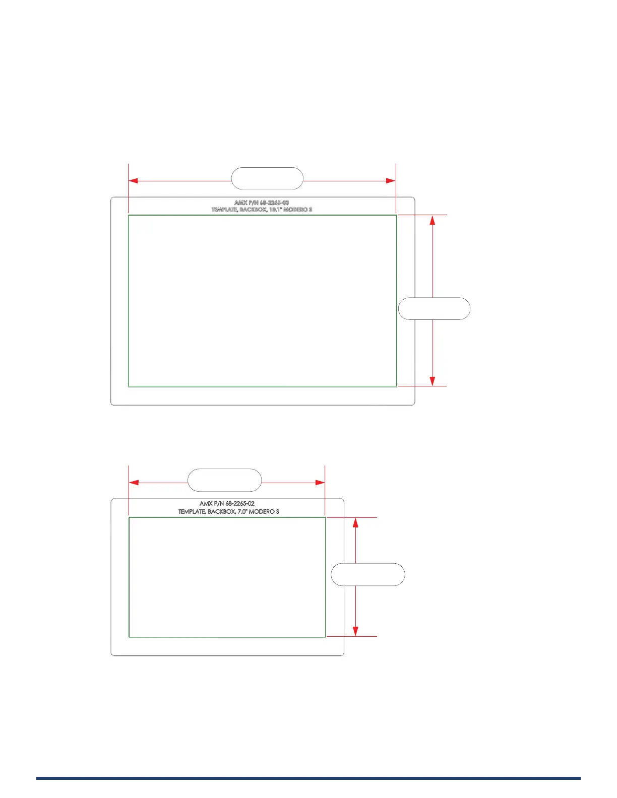
Cutouts
1. After ensuring proper placement, cut an opening in the mounting surface for the Backbox, using the included Installation
Template as a guide. For reference purposes, the cutout dimensions for each Modero wall mount panel is indicated below:
NOTE: Consider making the actual cutout opening slightly smaller than the provided dimensions. This provides a margin of
error if the opening needs to be expanded. Too little wall material removed is always better than too much.
MD-1002 - Cutout Dimensions
FIG. 23 MD-1002 Cutout Dimensions
MD-702 - Cutout Dimensions
FIG. 24 MD-702 Cutout Dimensions
NOTE: When installing the Backbox, make sure that the assembly is in the correct position and in the correct place. Once the
locking tabs are extended and locked into place, removing the Backbox may be dicult without having access to the back of
the wall or causing damage to the wall.
9.32" (+.01, -.00)
236.65mm (+.25, 0)
5.96" (+.01, -.00)
151.46mm (+.25, 0)
6.64" (+.01, -.00)
168.71mm (+.25, 0)
4.07" (+.01, -.00)
103.43mm (+.25, 0)
 Loading...