Overview
17
Hardware Reference Guide - NX-Series NetLinx Integrated Controllers
NX-3200 Specifications (Cont.)
Rear Panel Components: (Cont.)
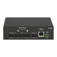
Relays (Port 21): 8-channel single-pole single-throw relay port
Each relay is independently controlled.
Supports up to 8 independent external relay devices
Channel range = 1-8
Each relay can switch up to 24 V
DC
or 28 V
AC
@ 1 A
Two 8-pin 3.5 mm mini-Phoenix (male) connectors provide connection to relays
Digital I/O (Port 22): 8-channel binary I/O port for contact closure with each input being capable of voltage sensing. Input format is
software selectable with interactive power sensing for IR ports.
IR/Serial
(Ports 11-18):
8 IR/Serial control ports support high-frequency carriers of up to 1.142 MHz with each output being capable of
two electrical formats: IR or Serial.
8 IR/Serial data signals can be generated simultaneously.
IR ports support data mode (at limited baud rates and wiring distances).
SDHC Slot: 1 SDHC card slot for future use.
Configuration DIP
Switch:
The Configuration DIP Switch allows you to set boot-time operations (see the Configuration DIP Switch section on
page 32 for more information.)
ICSLAN Ports: 1 RJ-45 connector for ICSLAN interface
USB Port: 1 Type-A USB port for connecting a mass storage device for loading .tkn files, reading or writing configuration
files and log files, or updating the firmware on the unit.
ID Pushbutton: 1 black ID pushbutton used during boot to revert to factory configuration or factory firmware. Also used after
boot to toggle IP mode between Static and DHCP.
LAN 10/100 Port: RJ-45 connector provides TCP/IP communication. This is an Auto MDI/MDI-X enabled port, which allows you to
use either straight-through or crossover Ethernet cables.
The Ethernet Port LEDs show communication activity, connection status, speeds, and mode information:
• SPD (speed) - Yellow LED lights On when the connection speed is 100 Mbps and turns Off when the speed is 10
Mbps.
• L/A (link/activity) - Green LED lights On when the Ethernet cables are connected and terminated correctly, and
blinks when receiving Ethernet data packets.
AxLink Port: 2 4-pin 3.5 mm mini-Phoenix (male) connectors that provides data and power to external AxLink control devices.
Green AxLink LED indicates the state of the AxLink port.
Power Connection: 2-pin 3.5 mm mini-Phoenix (male) connector with retention screws provides power to the NX-3200.
General Specif ications:
Operating
Environment:
• Operating Temperature: 32° F (0° C) to 122° F (50° C)
• Storage Temperature: 14° F (-10° C) to 140° F (60° C)
• Operating Humidity: 5% to 85% RH
• Heat Dissipation (On): 22.5 BTU/hr
Included Accessories: • 1 2-pin 3.5 mm mini-Phoenix (female) PWR connector
• 2 4-pin 3.5 mm mini-Phoenix (female) AxLink connector
• 2 6-pin 3.5 mm mini-Phoenix (female) I/O connectors
• 2 8-pin 3.5 mm mini-Phoenix (female) Relay connectors
• 2 10-pin 3.5mm mini-Phoenix (female) RS232/422/485 connectors
• 6 5-pin 3.5mm mini-Phoenix (female) RS232 connectors
• 2 CC-NIRC, IR Emitters (FG10-000-11)
•2 removable rack ears
 Loading...

