Preliminary Technical
Data
Rev. PrA | Page 19 of 82
DPD Mode of
Operation
Description
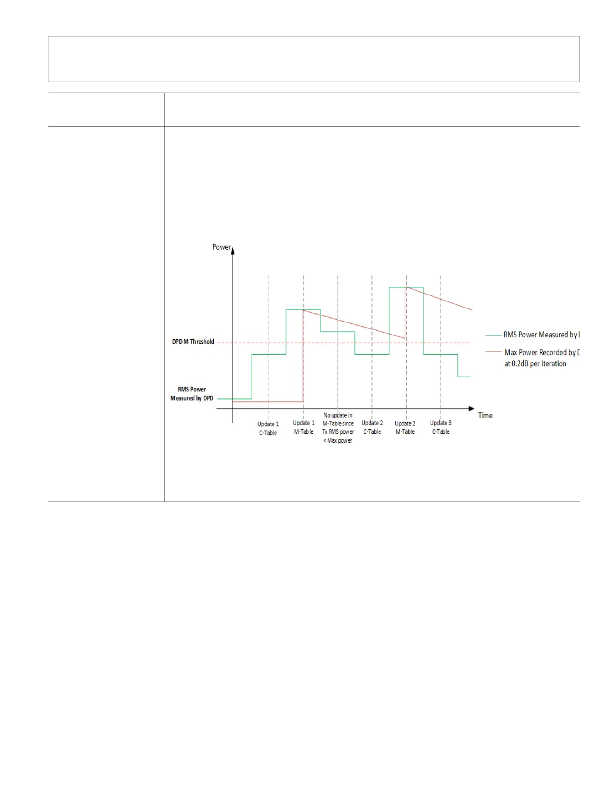
up table is active until the next DPD update. The RMS power threshold separating the low power
and high power region is user configurable through the parameter
adi_adrv9025_DpdTrackingConfig_t. dpdMThreshold. The RMS power is calculated on the
samples captured by the DPD for coefficient computation. The number of samples to capture for
a DPD update is specified by adi_adrv9025_DpdTrackingConfig_t.dpdSamples. Typically this is set
to 16384 samples.
Figure 22 is an illustration of DPD updates in Mode 2 operation.
Figure 22. Illustration of DPD Updates in Mode 2
This offers a compromise between modes 0 and 1. There is some mitigation of transient
emissions when the signal changes rapidly and sustained performance in many signaling
conditions.
Transmitter Low Power Threshold
The DPD continuously integrates the baseband power level at the input of the DPD actuator so that it can switch between the
different models described in Table 3. The power is measured for a period of 10 ms through a leaky integrator that runs
continuously in the background. If the 10 ms integrated rms power of the DPD input samples is below the transmitter low power
threshold specified by adi_adrv9025_DpdTrackingConfig_t.minAvgSignalLevel in linear scale, the unity gain table is activated, and
if the 10 ms integrated rms power of the DPD input samples is higher than the Tx low power threshold specified by
adi_adrv9025_DpdTrackingConfig_t.minAvgSignalLevel in linear scale, the DPD model defined by M-Table is activated in DPD
Mode 0 and Mode 1. In DPD mode 2, there is an additional threshold specified by
adi_adrv9025_DpdTrackingConfig_t.dpdMThreshold described in the next section. The dynamics of the DPD based on the
transmit baseband input level is shown in Figure 23.
 Loading...