Preliminary Technical
Data
Rev. PrA | Page 30 of 82
DPD Actuator Gain Monitoring + Model Switching State Machine Representation
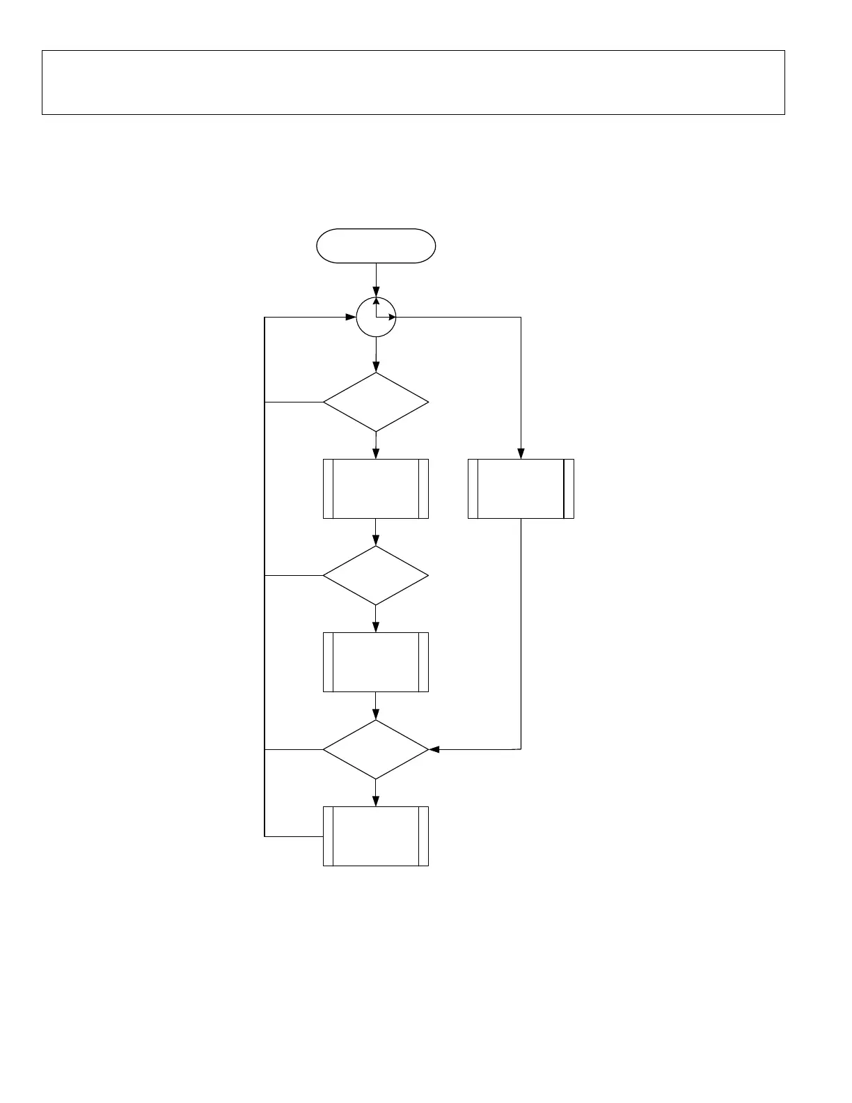
The flow chart in Figure 31 describes the function of the gain monitoring state machine. The DPD gain monitoring, once enabled,
runs independently from the DPD actuator. It monitors the gain of the signal across the actuator until it is turned off, as shown in
the state diagram.
Start
Sample Capture for
DPD Adaptation
Coeff Generation
and LUT Upd ate +
S et M /C Table as
active model
DPD Update
Conditions Met?
DPD Scheduled ?
Gain threshold
violation ?
Model Switch to
unity gain / R-Table
YES
Other Cals
FW Scheduling Timer
NO
NO
NO
YES
YES
YES
YES
Figure 31. DPD Gain Monitoring State Machine
 Loading...