Preliminary Technical
Data
Rev. PrA | Page 68 of 82
when ORx data is corrupted, and loop gain
estimated is bad. Setting the minimum Tx
attenuation limit ensures that the PA is not over
driven.
Maximum Tx Attenuation
The absolute value of the upper limit of Tx
attenuation configured in dB. Eg: If the upper Tx
attenuation limit is configured as 30dB, then the
CLGC algorithm cannot adjust the ADRV9025 Tx front
end attenuation beyond 30dB.
This parameter can be used to mitigate CLGC over-
compensating during any catastrophic situations
when ORx data is corrupted, and loop gain
estimated is bad. Setting the maximum Tx
attenuation limit ensures that the Tx front end
attenuation does not go under range.
adi_adrv9025_ClgcConfig_t.
clgcMaxTxAttenAdjust_dB
Tx Gain Adjustment Step
Maximum step size for adjusting the Tx attenuation
per CLGC update with a resolution of 0.05dB
adi_adrv9025_ClgcConfig_t.
clgcMaxGainAdjustmentStepSize_dB
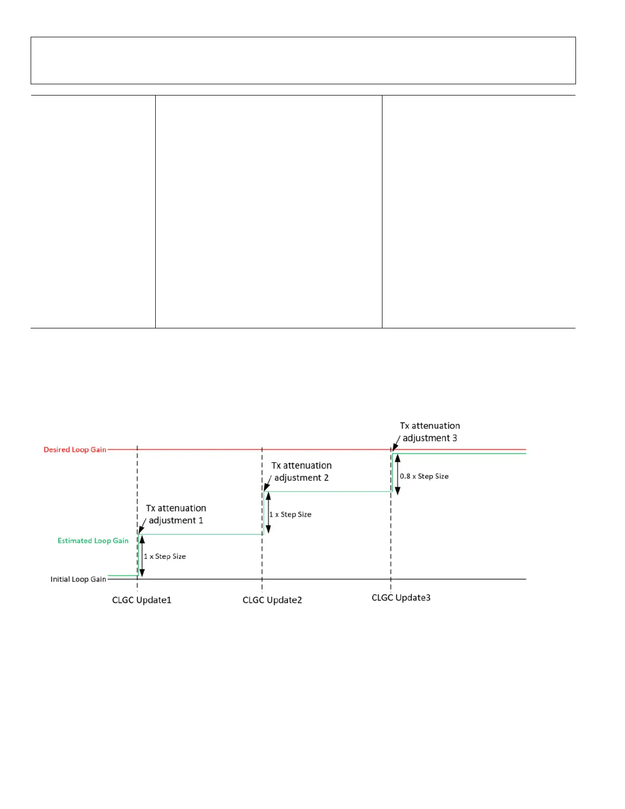
The Tx gain adjustment step size is a trade off between the time required to converge versus transient spectral emissions due. A
smaller Tx gain adjustment step results in smaller transient emissions, but takes a longer time to converge. A large step size
could result in transient emissions due to a large change in power, but the convergence time is lower compared to a smaller step
size.
An example is shown in Figure 68, where the desired loop gain is 2.8 x Tx gain adjustment step size relative to the initial loop
gain. The CLGC algorithm adjusts the Tx attenuation over 3 update periods to reach the desired loop gain as shown in the figure.
Please note that the CLGC update period is 1 second.
Figure 68. CLGC Loop gain convergence for 2.8x step size
Figure 8 represents the complete CLGC update cycle including the measurement and Tx attenuation control for a single CLGC
update. The flow diagram represents the measurement and update for a single CLGC update cycle.
 Loading...