EasyManuals Logo

Analog Devices EVAL-AD2428WD1BZ User Guide

Analog Devices EVAL-AD2428WD1BZ
6 pages
To Next Page IconTo Next Page
To Previous Page IconTo Previous Page
Page #4 background imageLoading...
Page #4 background image
Page 4 of 6
Jumper
LPS
Comments
JP1 (A2B power)
Install
-
JP2
Uninstall
Install when phantom power or hybrid power support is required
JP3
Uninstall
JP4 (BOOT)
Install
Self-Boot option disabled
JP5 (BCLK)
3-4-5
AD2428_BCLK -> ADAU1452_BCLK_OUT0 & ADAU1452_BCLK_IN0
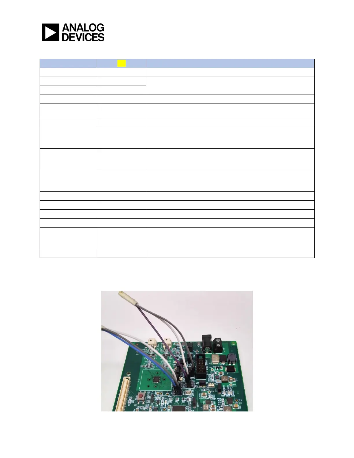
(Use a three-way wire connector See picture below)
JP6 (SYNC)
JP5(3-4) & JP7(5)
AD2428_SYNC -> ADAU1452_LRCLK_OUT0 & ADAU1452_LRCLK_IN0
JP7 (DRX0)
3-4
ADAU1452_SDATA_OUT0 -> AD2428_DRX0
JP7.5 should be connected to SYNC signals on JP6.3 & JP6.4
(Use a three-way wire connector See picture below)
JP8 (DRX1)
2-3
ADAU1452_SDATA_OUT1 -> AD2428_DRX1
If Secondary Rx data line DRX1 is desired. Uninstall if only primary
data line DRX0 is required.
JP9 (DTX1)
3-4
AD2428_DTX1 -> ADAU1452_SDATA_IN1
If Secondary Tx data line DTX1 is desired. Uninstall if only primary
data line DTX0 is required.
JP10 (DTX0)
1-2
AD2428_DTX0 -> ADAU1452_SDATA_IN0
JP11 (ADMP621 CLK)
Uninstall
-
JP12 (NTC)
Install
-
JP13 (A2B_REG)
Uninstall
-
JP14 (VOLTAGE)
Uninstall
Install depending on VIN requirement.
Installed -> VIN = 7V
Uninstalled -> VIN = 8V
JP19 (1961 BCLK)
1-2
ADAU1761 MCLK from CLKOUT of ADAU1452
LPS board Jumper Connections

Other manuals for Analog Devices EVAL-AD2428WD1BZ

Questions and Answers:

Question and Answer IconNeed help?

Do you have a question about the Analog Devices EVAL-AD2428WD1BZ and is the answer not in the manual?

Analog Devices EVAL-AD2428WD1BZ Specifications

General IconGeneral
BrandAnalog Devices
ModelEVAL-AD2428WD1BZ
CategoryMotherboard
LanguageEnglish

Related product manuals