EVAL-ADAU1701MINIZ
Rev. 0 | Page 3 of 12
SETTING UP THE EVALUATION BOARD
QUICK START
To quickly get started with the evaluation board, install the
SigmaStuido software, plug in the USBi, power up the board,
connect the audio cables, and set the switches and jumpers.
INSTALLING SIGMASTUDIO SOFTWARE
1. Open the provided zip file and extract the files to your PC.
Alternately, insert the SigmaStudio CD into the PC optical
drive and select the SigmaStudio folder.
2. Install Microsoft .NET Framework version 2.0, if it has
not been previously installed. To do so, double-click
dotnetfx.exe.
3. Double-click setup.exe and following the prompts. A
computer restart is not required.
SETTING UP THE HARDWARE
1. Plug in the USBi into the control port on the evaluation
board (see Figure 2).
2. Connect the USB cable to your computer and to the USBi.
3. When prompted for a driver, select Install from a list or a
specific location.
4. Select Search for the best driver in these locations.
5. Check the box for Include this location in the search.
The USBi driver is located in C:\Program Files\Analog
Devices Inc\Sigma Studio\USB drivers.
6. Click Next.
x If prompted to choose a driver, select CyUSB.sys.
x If a message appears in XP stating that the software
has not passed Windows Logo testing, click Continue
Anyway.
POWERING UP THE BOARD
The evaluation board can be powered either by the USBi or by
the power supply provided with the board. For the board to run
independently from the computer, disconnect Jumper J3 and
connect the power supply at J2 (see Figure 2). The power
indicator LED, D3 (see Figure 2). should be lit.
CONNECTING THE AUDIO CABLES
Set up the evaluation board by connecting the stereo analog
inputs and stereo analog outputs, using 1/8” cables. To do so:
1. Connect the audio source to the input J5 jack (see Figure 2).
2. Connect the output J6 jack to your speakers or headphones
(see Figure 2).
SETTING SWITCHES AND JUMPERS
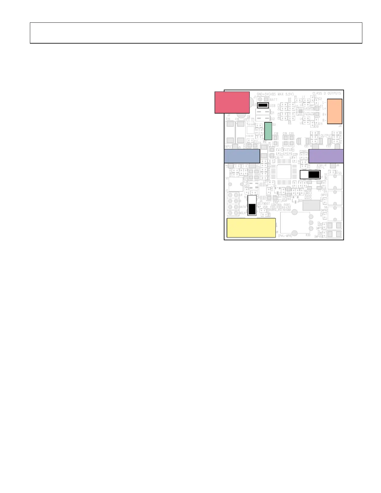
To configure the evaluation board for stereo analog input and
output, set the switches and jumpers as shown in Figure 2.
07720-030
OUTPUT
J6
INPUT
J5
CONTROL PORT
J8
AMPLIFIER
OUTPUTS
POWER
INDICATOR
J3
J4
S1
S5
POWER JACK
J2
L–
L+
R+
R–
D3
Figure 2. Evaluation Board Setup and Configuration
THE FIRST SIGMASTUDIO PROJECT—EQ FILTER
AND AUX VOLUME CONTROL
To create a new SigmaStudio project, follow the steps outlined
below. To complete the steps, you will be working with the
Hardware Configuration tab of the software shown in
Figure 3.
1. Drag an ADAU1701 and a USBi cell from the Tree
ToolBox into the blank white space of the Hardware
Configuration tab. If you are using a processor other
than the ADAU1701 (for example, the ADAU1401 or
the AD
AU1702), then drag that processor.
2. Co
nnect the USBi cell to the ADAU1701 cell by clicking
and dragging from the top blue output pin to the green
input pin. Your screen should now appear as shown in
Figure 3.

 Loading...


