EVAL-ADAU1701MINIZ
Rev. 0 | Page 6 of 12
08060-006
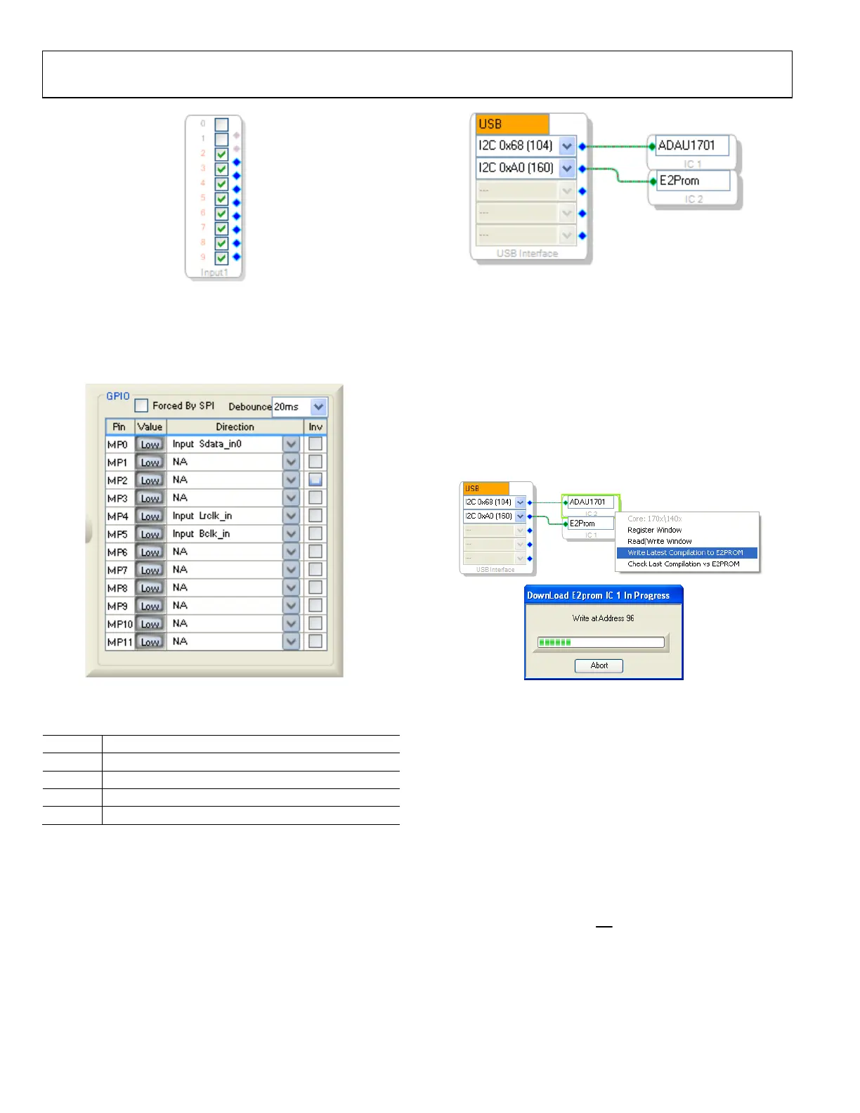
Figure 6. Digital Audio Input 0 through Input 7 in SigmaStudio Input Cell
Configure the corresponding multipurpose pins of the
ADAU1701 in SigmaStudio, as shown in Figure 7. Note that
these are different pins than those used for serial data input,
thus ensuring that there will be no conflict.
08060-007
Figure 7. Multipurpose Pin Configuration in SigmaStudio for
Digital Audio Input
Table 3. Analog and Digital Audio Connectors
Jack Function
J4 Amplifier output speaker terminals
J5 Stereo analog line input
J6 Stereo analog line output
J7 Serial data input
I
2
C COMMUNICATIONS HEADER
The I
2
C communications Header J8 connects to the ADAU1701
communications port. Along with the I
2
C signals, a DSP reset
signal and USB bus power are included on J8. Typically, the
USBi (EVAL-ADUSB2) is connected to this header to enable
communications with SigmaStudio. The SigmaStudio hardware
configuration for this setup is shown in Figure 8.
08060-010
Figure 8. Using the EVAL-ADAU1701MINIZ and the USBi with SigmaStudio
SELF-BOOT EEPROM
SigmaStudio can download a single set of program RAM,
parameter RAM, and register settings to the EVAL-
ADAU1701MINIZ self-boot EEPROM. To do this, disable
the write-protect Switch S5 (set the switch in the down
position).
To download from SigmaStudio to the EEPROM, compile the
project, then right-click the ADAU1701 in the Hardware
Configuration tab and select Write Latest Compilation to
E2PROM, as shown in Figure 9.
08060-012
Figure 9. SigmaStudio Downloading to Self-Boot EEPROM
The ADAU1701 automatically self-boots any time the board
is powered and the EEPROM contents are valid. Press the reset
switch (S2) to ensure that the ADAU1701 self-boots while the
board power remains on.
GPIO INTERFACE
The ADAU1701 has 12 multipurpose pins that can be used as
digital GPIO or auxiliary ADC inputs. On the EVAL-
ADAU1701MINIZ, Pin MP1, Pin MP10, and Pin MP11 are
connected to LEDs and used as outputs. Pin MP2, Pin MP3,
and Pin MP9 are connected to push-buttons and pull-up
resistors and are used as inputs. Pin MP8 is connected to a
linear potentiometer and used as an input to the auxiliary ADC.
Pin MP7 is connected to the
SD
pin of the SSM2306 amplifier.
This allows the ADAU1701 SigmaDSP to control the power-
up/power-down of the SSM2306.

 Loading...


