EVAL-ADAU1701MINIZ
Rev. 0 | Page 7 of 12
Table 4 shows the ADAU1701 pins connected to the different
GPIO functions and the associated settings.
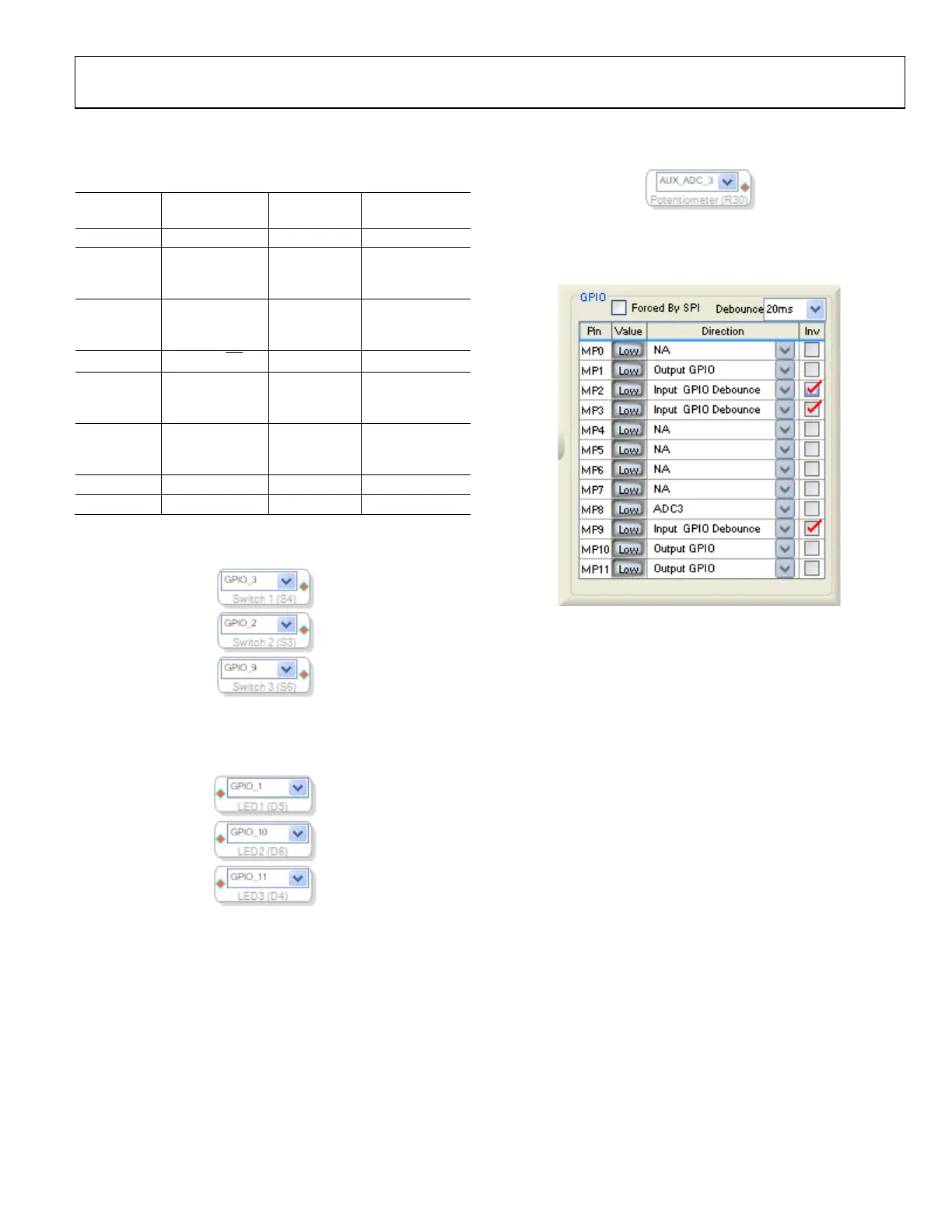
When used in SigmaStudio, the potentiometer input to the
auxilliary ADC appears as shown in Figure 12.
Table 4. GPIO Setup
08060-016
ADAU1701
Pin Device Settings
SigmaStudio
Setting
MP1 Yellow LED D5 Active high Output GPIO
MP2 Push-button S4
Push to
ground
Input GPIO
debounce,
invert
MP3 Push-button S3
Push to
ground
Input GPIO
debounce,
invert
MP7
SSM2306 SD
Figure 12. Potentiometer Input in SigmaStudio
The settings in the SigmaStudio register control window appear as
shown in Figure 13 when used with the EVAL-ADAU1701MINIZ.
Active low Output GPIO
MP8
10 kΩ
potentiometer
Clockwise
turn lowers
resistance
ADC3
MP9 Push-button S6
Push to
ground
Input GPIO
debounce,
invert
MP10 Yellow LED D6 Active high Output GPIO
MP11 Red LED D4 Active high Output GPIO
When used in SigmaStudio, the input push-buttons appear as
shown in Figure 10.
08060-017
Figure 13. SigmaStudio Multipurpose Pin Configuration for the
EVAL-ADAU1701MINIZ
WRITEBACK TRIGGER TRANSISTOR
08060-014
The writeback trigger transistor circuit is intended to send a
high pulse to the ADAU1701 WB pin when the power supply
(DVDD) is interrupted. During normal operation, DVDD is
high (+5 V), so Transistor Q2 is always turned on, and the WB
signal is held low.
Figure 10. Push-Button Inputs in SigmaStudio
When used in SigmaStudio, the output LEDs appear as shown
in Figure 11.
08060-015
When the power supply (DVDD) is removed, the transistor
turns off, sending a high pulse on the WB signal line to the
ADAU1701. The two large 220 μF capacitors on the regulator
hold DVDD high until the data writeback transfer is complete,
thus providing adequate supply voltages to the ADAU1701 and
the self-boot EEPROM.
RESET
Figure 11. LED Outputs in SigmaStudio
The ADM811 provides a clean active-low reset signal to the
ADAU1701 when Switch S2 is pressed.
 Loading...


