Device description and principle of operation
SPECORD PLUS Edition 03/2013 21
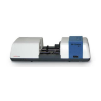
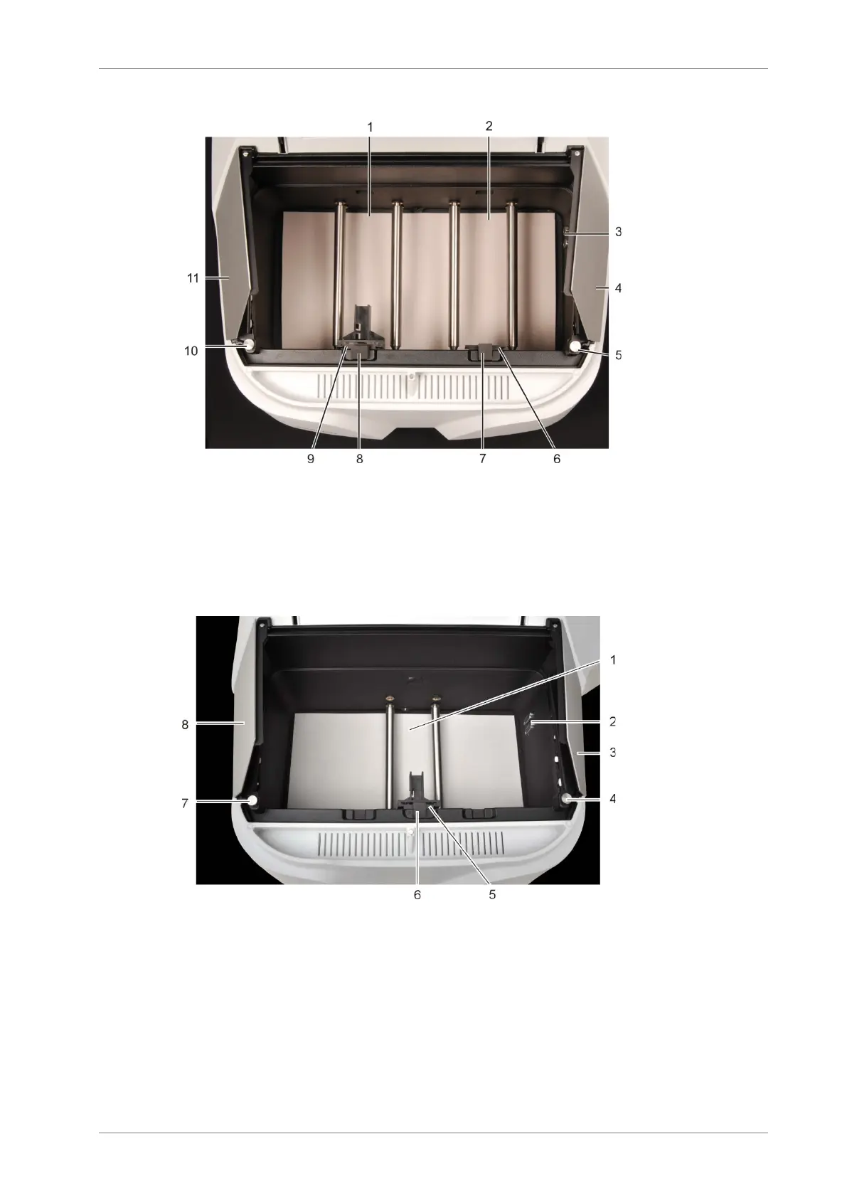
1 Measuring beam path
2 Comparison beam path
3 Connections for electrical accessories
4, 11 Removable side components
5, 10 Attachment screws for side components
6, 9 Plates to accept the cell holders
7, 8 Cell ducts to accept dispersing samples
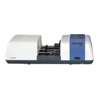
Fig. 5 Sample chamber of the SPECORD 200/210/250 PLUS (from the top)
1 Measuring beam path
2 Connections for electrical accessories
3, 8 Removable side components
4, 7 Attachment screws for side components
5 Plates to accept the cell holders
6 Cell ducts to accept dispersing samples
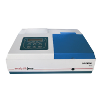
Fig. 6 SPECORD 50 PLUS sample chamber
In the left sample chamber wall are the connection sockets for the electrical accessories or
the identification connectors of the accessories. The left and right sample chamber wall can
be removed after removing the attachment screws. In the left and right sample chamber wall
there are 4 ducts each of various sizes sealed with gray plugs and plastic stoppers.
 Loading...