FL 128 Multizone System 15.01.2021 38
Fixing
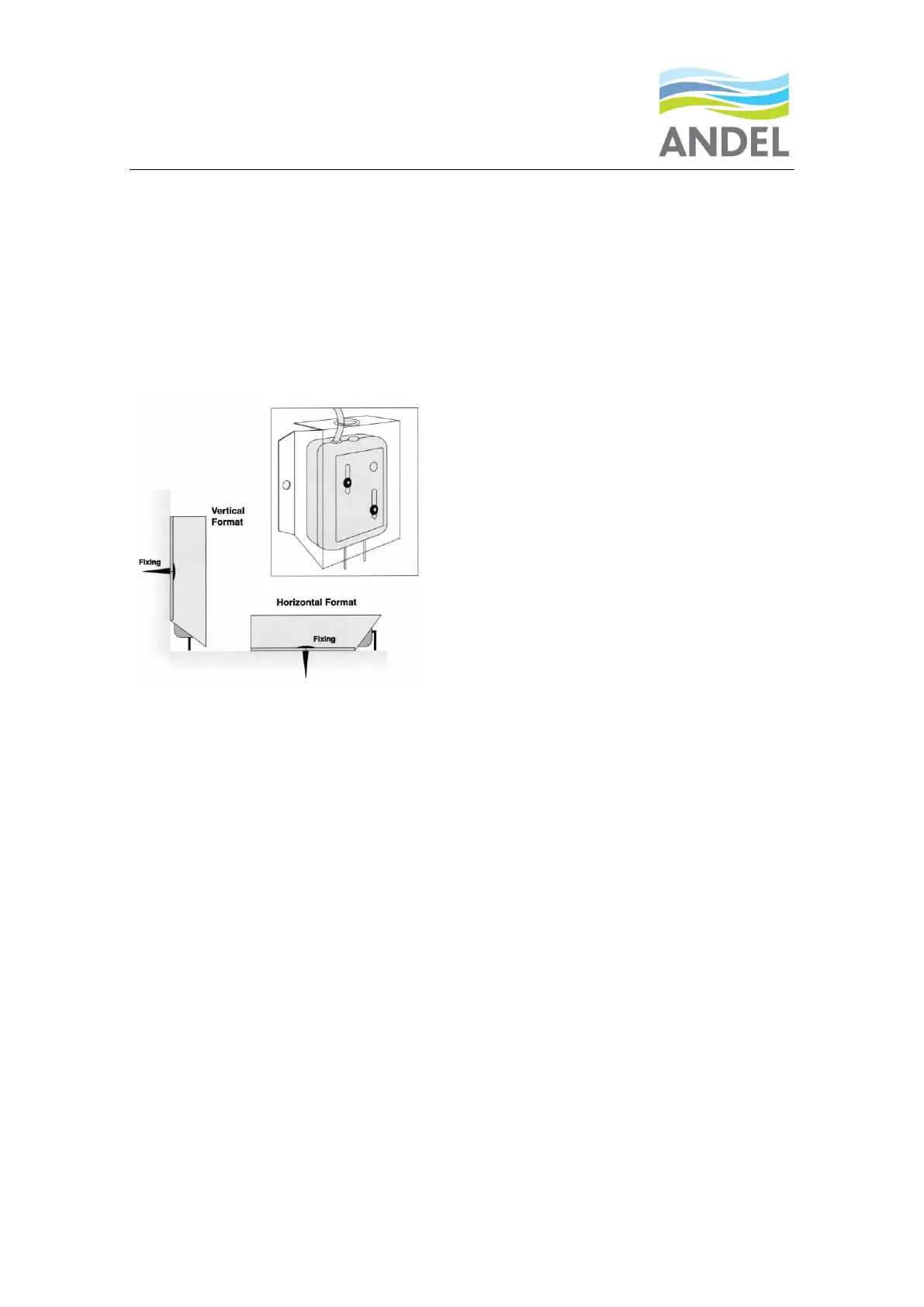
Point sensors are almost always used in conjunction with the Guard Plate to assist fixing, adjustment
and to protect the sensor from accidental damage by cleaners or other abuse.
The Vertical Point Sensor is mounted at the base of the wall, plinth or item of apparatus. The sensor is
first fixed to the guard plate using 2 no 4x3/8” self-tapping screws fixed through adjustment slots in the
guard plate and into the two offset holes pre-drilled in the point sensor. The guard plate should cup
around the point sensor. The guard plate and sensor assembly can then be fixed to the wall etc with
screws/bolts through the holes provided in the flanges of the guard plate.
Once the assembly is fixed at the desired height above the floor the sensor probe tips can be adjusted
up or down by loosening the 2 staggered fixing screws and sliding the unit up or down within the guard
plate. A recommended gap between the floor and the tips of the probes can be judged by placing a thin
piece of card (a business card is good) on the floor and allowing the tips to rest on it. The staggered
fixing screws can then be tightened, and the card removed. This will give a gap of around 0.5 to 1mm
but larger gaps can be used if required.
Where it is not possible to fix to the wall surface or other convenient surface the assembly can be bolted
to struts or other fabricated bracket and special right angle supports are available from Andel.
The Horizontal Point Sensor must be used in conjunction with a guard plate and can be mounted on any
flat surface with the tips of the sensing probes facing downwards. The distance from the tip of the
probes to the floor is pre-set at the factory at around 1.5mm. There is no operational need for the
assembly to be fixed to the floor, but it is recommended, and screw holes are provided. Gluing and self-
adhesive pads are acceptable if the substrate is suitable.
Connecting to the Floodline Panel
All types of Point Sensor will be connected to the zone input terminals of the Floodline control panel via
2 core (minimum) leader cable. The minimum specification of the leader cable from the panel to the
point sensor is standard PVC/PVC 7/0.2mm multi-core alarm/comms type cable or similar. LSF or other
light cables can be substituted if required. A zone can consist of a single point sensor or any number of
point sensors connected as a “string” or “daisy-chain”. Input and output terminals are provided in each
point sensor to allow for this purpose.


 To Next Page