Section 1–Controller Setup ATC200-Lite Teletilt
®
Remote Control Downtilt System
1-2 May 2005 Bulletin 639510
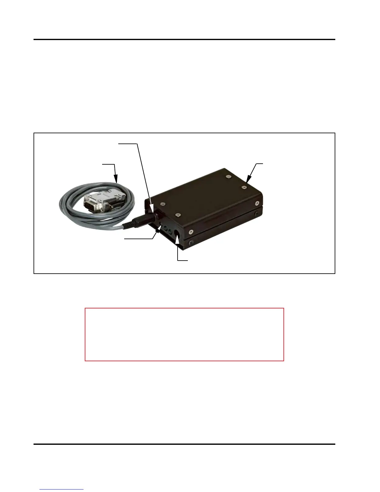
Figure 1-1. ATC200-Lite Controller with RS-232 Serial Cable Attached.
2. Connect the supplied 24Vdc or 12Vdc power converter to the dc IN port on the controller
(Figure 1-1). IMPORTANT NOTE: The power converter used will affect both the 12Vdc
and 24Vdc connector pins. For example, if a 24Vdc power converter is used, both
the 12Vdc and the 24Vdc connector pins will transmit 24Vdc power.
3. Connect the desired length RET control cable between the controller’s 8-Pin DIN connector
(RS-485 RET port, located on the back panel) and the rst component in the RET system.
See Figures 1-1 and 1-2 and Section 10 for a brief description of system components.
RS-232 Serial Port
dc IN Port
LEDs on
Front Panel
RS-485 RET Port
RS-232 Serial
Cable, Supplied
IMPORTANT
DISCONNECT THE ATC200-Lite CONTROLLER FROM THE
RET SYSTEM AT THE END OF EACH SESSION TO PREVENT
POSSIBLE DAMAGE TO RET DEVICES.
 Loading...