Before Assembly After Assembly
Before Assembly After Assembly
Length of A8 Components Wire
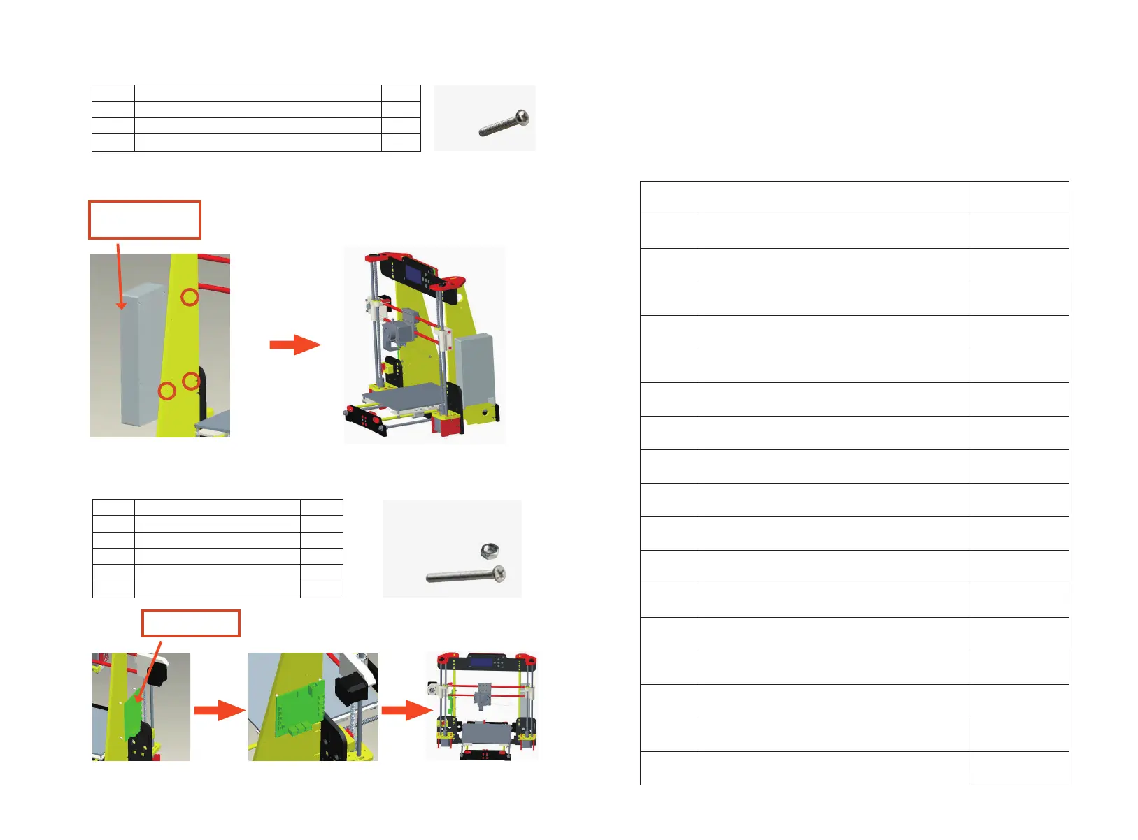
Orange circles stand for the power screw holes.
Attention: Please use the corresponding wire , especially motor
wire & limited switch wire.
Item
1
2
1
1
QTY.
NO. Option Length(mm)
650mmPower supply wire
X motor wire
Y motor wire
Left Z motor wire
Right Z motor wire
X limited switch wire
Y limited switch wire
Z limited switch wire
Extruder motor wire
4010 Fan wire
5015 Blower wire
Heating pipe wire
Extruder thermistor
Hotbed wire
X Belt
Y Belt
Screen wire
400mm
400mm
400mm
900mm
900mm
1100mm
1100mm
1000mm
1000mm
900mm
1700mm
500mm
500mm
500mm
200mm
Name of parts
Step 25
Power supply 12V
3
1
2
3
4
5
6
7
8
9
10
11
12
13
14
15
16
17
3M3*12 screw
Step 26 Step 28
Item
1
2
3
1
1
4
QTY.Name of parts
Step 26
Mainboard
M3-30 screw
4
5
4
4
M3 Nut
Pillar washer M3*15
Step 27
M3*30
M3*15
M3
Power Supply
Mainboard
M3*12
page 24 page 25