Manual Functions
Document No. 992012. Issue 16 – 12.01.21
Page 11
7. Introduction to Manual Functions
This section of the document gives a description of product functions that are manually
operated, and how to use them. Some of the manual functions are common across the
product range, and are relevant to DRIVE, DRIVE Powered and Powered trolleys.
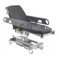
8. Height Adjustment
The height of the patient platform is adjusted by using either of the raise and lower
pedals (item 5, Fig.2). Pumping either pedal will raise the patient platform, lifting either
pedal will lower the patient platform.
WARNING: Ensure there is nothing to impede the raising or lowering of the
patient platform as this could result in damage to the equipment and/or injury
to the patient.
WARNING: When leaving patients unattended the trolley should be fully
lowered to minimise any risk of injury should the patient fall off the trolley.
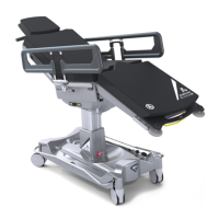
9. Using the Brakes
All four castors are simultaneously braked by depressing either of the brake pedals at
any point along the length of the pedal (item 4, Fig.2). The brakes are disengaged by
lifting either pedal.
WARNING: Always apply the brakes when leaving a patient unattended, a
patient is getting on or off the trolley, or transferring patients from the trolley
to another platform.
10. Using the Steering Pedal, activates 5
th
wheel
The trolley can be manoeuvred more easily by engaging the 5
th
wheel steering
mechanism (item 3, Fig.2). NOTE: This is a non-powered 5
th
wheel, see Section 17.
‘Introduction to DRIVE Assist’, for details about the powered DRIVE assist wheel option.
The mechanism is engaged, and disengaged, by pressing down on the steering pedal. To
move the trolley sideways disengage the 5
th
wheel.
CAUTION: Applying the steering pedal with excessive force, i.e. by standing on
it, may cause permanent damage to the mechanism.
11. Using the Side Rails
The trolley is fitted with two side rails that can be individually raised and lowered (item
6, Fig.2). Lower the side rail by pulling up on the side rail release lever (item 7, Fig.2)
and pushing the side rail down. Raise the side rail by gripping it and pulling up firmly
to its full height; the release lever will make an audible ‘CLICK’ when engaged. The side
rail will now be locked into position.
WARNING: It is important to ensure that nothing impedes the side rail release
lever from locking correctly; ensure that the release lever remains visible at all
times.
WARNING: After raising the side rail it is important to ensure that the release
lever has properly locked in position by pushing down firmly on the side rail.
Failure to ensure the side rail is properly locked could result in injury to the
patient.
CAUTION: If the side rail mounted IV pole is in use when either raising or
lowering the side rail it is important to check the infusion flow rate as the
height of the infusion above the patient will change by approximately 30cm.
The side rails are designed to prevent a patient inadvertently rolling off the
trolley; they are not intended to restrain the patient.