SLG I&O Series
8
3 Lighting Instructions
For manual pilots, refer to the following instructions.
Warning
If pilot extinguishes, wait 5 minutes before attempting to relight the pilot to
allow any built up gas to dissipate.
a. Open gas supply valves to the appliance.
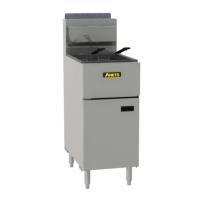
b. Turn the thermostat control knob counterclockwise to the OFF position.
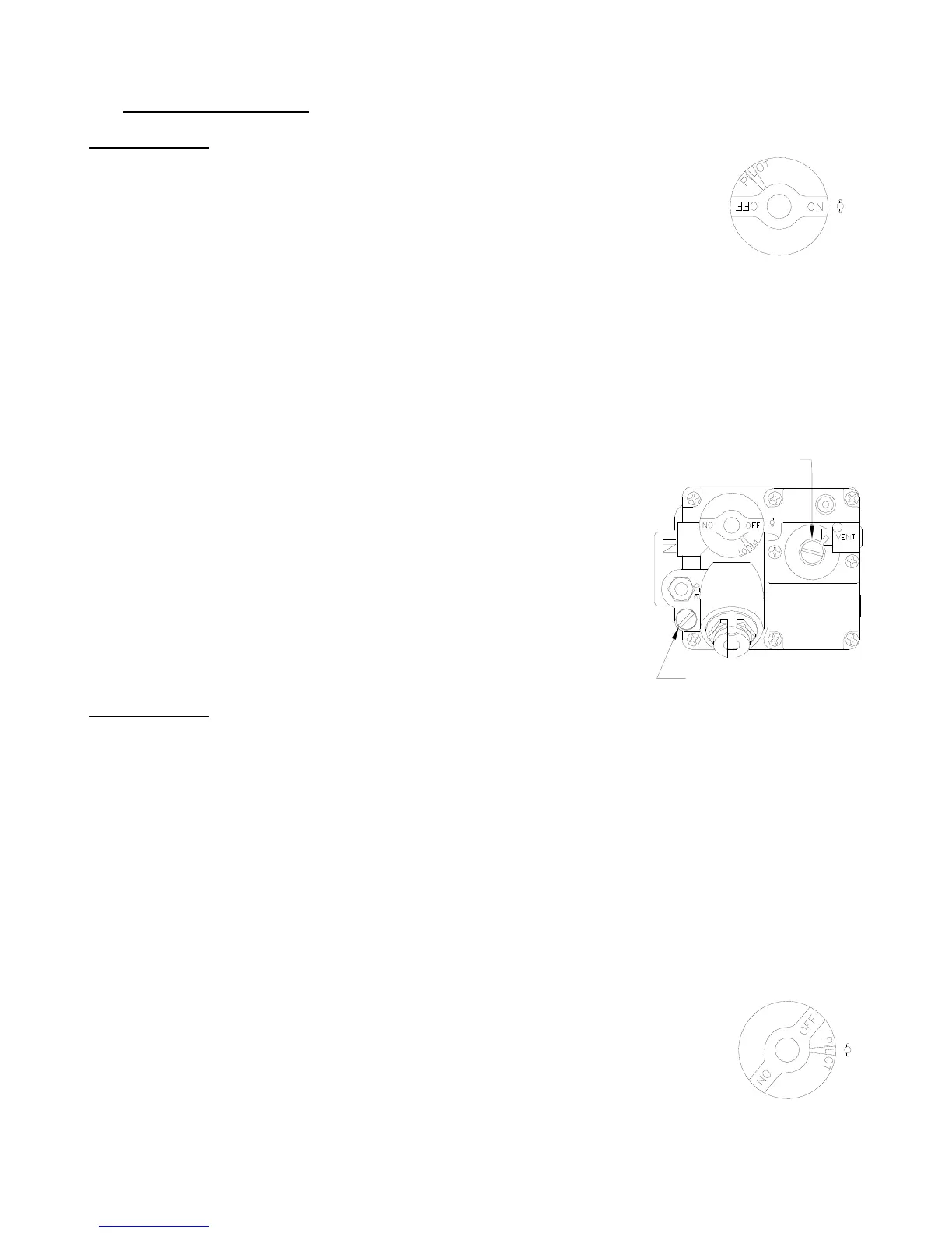
c. Turn the gas valve knob to the PILOT position. Push in on the knob while pressing the
ignitor button or hold a flame to the pilot until the pilot ignites; this may take a little while
the first time you light the pilot because of the air in the lines. Once lit, hold the knob in for
approximately one minute and then release.
d. If the pilot goes out, wait 5 minutes and repeat step C. If after
three tries the pilot will not remain lit, refer to the operator
troubleshooting section of this manual.
e. Once a pilot flame has been established, turn the gas valve
knob counterclockwise to the ON position.
f. Set the thermostat control knob to the desired temperature
setting.
The main burners will ignite and be controlled by the
thermostat.
3.1 Pilot Flame Adjustment
For manual pilots
, refer to the following instructions. Perform this procedure once the pilot is lit.
NOTE: This procedure requires a DC millivolt meter set to a scale of 0-1000 mV.
Using test leads with sharp probes will help in taking the required readings.
a. Locate the thermopile wires coming from the thermostat/limit box going to the gas valve.
The wire size decreases near the gas valve connections.
b. Using the positive (+) test probe, connect the probe to the high limit wire terminal. On
UFM systems, pierce the high limit wire insulation, with the tip of the test lead probe, at
the gas valve safety magnet connection.
c. Connect the negative (-) test probe to the pilot tubing.
d. Remove the cap screw located below the pilot tubing on the gas valve. The pilot flame
adjustment screw is recessed behind this. Turning the pilot flame adjustment screw
clockwise
lowers the pilot flame and millivolt output. Turning the pilot flame
adjustment screw counter- clockwise increases the pilot flame size
and millivolt output.
e. While monitoring the DC millivolt meter, rotate the pilot flame adjustment
screw in the direction necessary to achieve a reading of 400 ± 50mV.
Note: Allow 3 to 5 minutes between flame adjustments to allow the reading to stabilize.
REGULATOR ADJUSTOR
(UNDER CAP SCREW)
PILOT ADJUSTOR
(UNDER CAP SCREW)