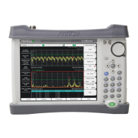
Do you have a question about the Anritsu S331E and is the answer not in the manual?
Explains danger, warning, and caution symbols used in manuals.
Details symbols found on equipment and in manuals for operations.
Overview of the manual's content and scope for Site Master models.
Contact information for Anritsu sales and service support.
Lists essential test equipment for verifying Anritsu Site Master functions.
Catalog of parts that can be replaced on the Site Master units.
Procedure to verify and adjust the CW frequency accuracy of the Spectrum Analyzer.
Test procedure to verify the single side band (SSB) phase noise performance.
Verifies input related spurious response, specifically second harmonic distortion.
Verifies the resolution bandwidth accuracy of the spectrum analyzer.
Verifies the absolute amplitude accuracy of the spectrum analyzer.
Verifies residual spurious response using positive peak detection mode.
Verifies the displayed average noise level (DANL) using RMS detection mode.
Verifies the Third Order Intercept point (TOI or IP3) of the spectrum analyzer.
Verifies the CW frequency accuracy in Cable and Antenna Analyzer mode.
Verifies the accuracy of return loss measurements in Cable and Antenna Analyzer mode.
Introduces the verification processes for available options on the S3xxE Site Master.
Verifies the functionality of the optional Bias Tee in Cable and Antenna Analyzer mode.
Verifies system dynamic range for 2-Port Transmission Measurement option.
Verifies the level accuracy of the Power Meter with Option 29 installed.
Verifies the functionality of the GPS option on the S3xxE Site Master.
Provides general information on the care and handling of Anritsu battery packs and Lithium-Ion batteries.
Instructions for removing and replacing the Site Master battery pack.
Provides instructions for opening the Site Master case for internal access.
Instructions to remove the Motherboard/VNA and SPA assemblies from the case.
Instructions to remove and replace the SPA (Signal Processing Assembly).
Procedure to replace the N connector attached to the SPA or MB/VNA assembly.
Instructions to replace the GPS assembly (Option 31).
Instructions to replace Ethernet (Option 411) or CPRI (Option 751) assemblies.
Instructions to replace the main Motherboard/VNA assembly.
Procedure to replace the internal fan assembly.
Instructions to replace the liquid crystal display (LCD) assembly.
Procedure to replace the LCD backlight PCB.
Instructions for replacing the rubber keypad and keypad PCB.
Procedure to replace the touch screen assembly.
Describes primary troubleshooting operations performed by Anritsu Service Centers.
Addresses issues when the unit fails to boot up or complete the boot process.
Covers issues like unresponsive touch screen, charging, lock errors, and PCB failures.
Provides tables to record Spectrum Analyzer performance verification data.
Provides tables for recording Cable and Antenna Analyzer performance verification.
Provides tables for recording the verification of various instrument options.
| Impedance | 50 ohms |
|---|---|
| Distance-to-Fault (DTF) | Yes |
| GPS | Optional |
| Display | 5.7 inch color LCD |
| Battery Life | 4 hours |
| VSWR | 1.0 to 65 |
| Power Supply | 100-240 VAC, 50/60 Hz |


 Loading...